What is in the circles?

7173Mustangs.com

Help Support 7173Mustangs.com:

This site may earn a commission from merchant affiliate links, including eBay, Amazon, and others.

Vinnie

Project manager "Project AmsterFoose"
7173 Mustang Supporter Member
Joined
Nov 7, 2013
Messages
1,594
Reaction score
286
Location
Amsterdam, The Netherlands
My Car
1973 Mustang Grande 351C 2V, built on the very last production day (July 6, 1973) for Grande's.
Hey guys,

Everytime I'm checking the wiring diagrams I'm never sure what it is inside these circles:

IMG_0715.jpg


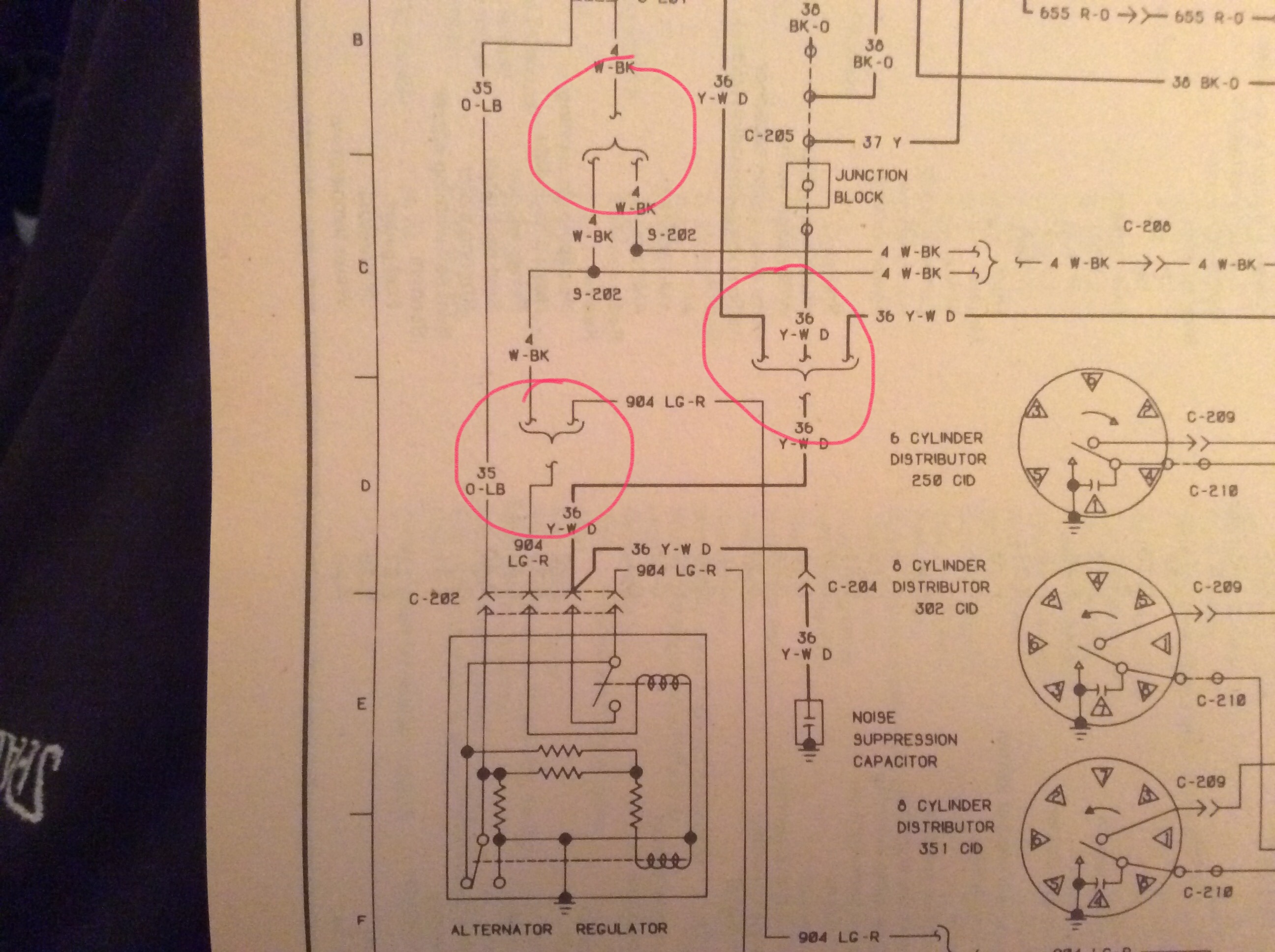
Does 1 wire split in two? Or does it go one way or the other depending on a certain part being present (elec. choke for instance).

If someone can please explain how to read the inside of these circles (in general, not specifically these) that would be much appreciated :)

Thanks,

Vincent.

 
It is a splice, signified in the harness by a big black rubbery sleeve looking thing.

 
Negative on splice. What that diagram means is that there are two versions of the wiring, depending upon application. In this particular case, you'll looking at the wiring for the voltage regulator/alternator, of which there is a version for the alternator indicator lamp (standard dash cluster) and ammeter (tach dash and/or 3 gauge center cluster where the ammeter resides). The VR circuitry is different depending upon which version you have.

 
Thanks both for your reply :)

I get the general idea but it leaves a bit of room for misinterpretation so I would like to make it clearer... In the bottom circle, wire 904 can connect to wire 4 AND/OR wire 904. Is it AND or OR? Or could it be both? What I'm uncertain about is if these situations are ALWAYS 1 on 1. Is there a rule about this?

Thanks,

Vincent.

 
It is OR, depending upon overall configuration. You cannot mix and match.

These schematics leave much to be desired for their preciseness.

 
It is OR, depending upon overall configuration.  You cannot mix and match.

These schematics leave much to be desired for their preciseness.
Thank you, that clarifies at least something. Doesn't make them easier to read though haha. They could also tell us a bit about which parts were optional then I guess.

 
Vincent, what I found helpful was to print a copy 'for my car' and draw a connection to indicate which one is used for my car. I actually used highlighter pen and would 'trace' the circuit, including the gap in the circles. This made it much easier to follow and understand.

Generally the diagram is easy to follow, even for a novice like myself. But I did find the alternator/amp meter wiring rather confusing. The combination of it being part of the charging circuit and the difference in wiring for an 'idiot light' vs an amp meter added to the confusion. I also didn't know about using a 'shunt' in the circuit or what that meant. Basically the charging circuit is split in to two separate wires in our cars when using the amp meter. Effectivly half of the power goes through each wire. This allowed Ford to run a smaller gauge wires to the Amp meter. This had a couple of advantages. Cost, since the smaller wire is less expensive and the amp meter design only has to handle half the power. And less chance of a fire. The AMP meter in my old jeep handles the full load and when the connectors gets old and loose from jiggling around in a car they create resistence which in turn generates heat. It is not unusual for the dash to catch fire.

 
Vincent, what I found helpful was to print a copy 'for my car' and draw a connection to indicate which one is used for my car.  I actually used highlighter pen and would 'trace' the circuit, including the gap in the circles.  This made it much easier to follow and understand.
Yeah, I was thinking of doing that too. I'll get there :)

 
I'm not sure if this would help with the problem, but I purchased Forel Publishing Inc's 1971 Colorized Mustang Wiring and Vacuum Diagrams. CD ( also there is a Parts &Body Illustration CD and both are licensed by Ford) The website does not show them for other years, but an inquiry may be in order. I don't know how many differences there are between years. The CD's are installed on my desktop for easy reference. Just a note, these do need to be licensed when installing them, no big problem though.  www.ForelPublishing.com

While any wiring diagram is foreign to me, it may be clearer to the experts out there and assist our friend in need.

Geoff.

 
No, but there are funny modifications made a while ago that are no longer required so I want more original alternator wiring. Understanding what I should have allows me to pick and install the right one.

 
Back
Top