“73 Mach One HIE Ignition, solenoid, starter wiring

7173Mustangs.com

Help Support 7173Mustangs.com:

This site may earn a commission from merchant affiliate links, including eBay, Amazon, and others.

Robnbama

Well-known member
Joined
May 8, 2012
Messages
57
Reaction score
0
Location
Attalla, Alabama
My Car
1973 Ford Mustang Mach one


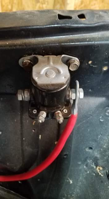
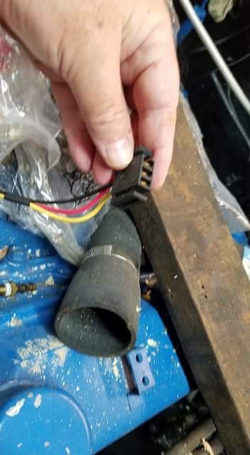
Hey everybody. I’m gettin started back on my ‘73 Mach One after years of it just sitting. I had to many projects going on. I’m at the point where I’ll be installing a HEI distributor and a fender apron mounted starter solenoid. The new HEI has a yellow, red and black wiring coming from the bottom. The starter solenoid has two larger nuts for the battery and starter wire and two other smaller nuts. One has an “I”and the other has an “s”. There is a original wiring harness goes along the front crossmember over towards the battery and has the following color coded wires. I just needed some input on where these wires would go. I’m pretty sure I have a one wire alternator with a built-in voltage regulator.


Big solid yellow wire 


Light green red stripe 


Red with green stripe 


Red with light blue stripe


White with black stripe 


After looking over the wiring diagram and a picture of the distributor I’m still lost. Is there anybody that could look on their wiring harness and see where the wires go? I know some goes to the solenoid some goes to the distributor and some goes to the alternator but I’m just not sure and I don’t want to fry my system.

 
Last edited by a moderator:
Link to the wiring diagrams on this site.

https://www.7173mustangs.com/misc.php?page=diagrams

The connector you're showing from the HEI plugs into the distributor cap. There are two other connections with blade terminals. One for switched power, the other is the tach feed.

chevy-350-hei-wiring-diagram-distributor-wiring-diagram-chevy-350-hei-spark-plug-wiring-diagram.jpg


Thanks guys. This should get me pointed in the right direction. I’m horrible with wiring diagrams.

 
Last edited by a moderator:
After looking over the wiring diagram and a picture of the distributor I’m still lost. Is there anybody that could look on their wiring harness and see where the wires go? I know some goes to the solenoid some goes to the distributor and some goes to the alternator but I’m just not sure and I don’t want to fry my system.

 
The HEI is self explanatory. The clip only goes in one way. The cap should even have markings molded into it.

Assuming you don't have the gauge package:

Big solid yellow wire - front stud of starter solenoid, along with BATT (+) cable

Light green red stripe - radio condensor (leave disconnected if you don't have one)

Red with green stripe - "I" terminal of starter solenoid

Red with light blue stripe- "S" terminal of starter soleoid

White with black stripe - Alternator "STA" terminal to "S" on the regulator connector

Rear post of solenoid goes to the starter

Negative on battery needs to go to the engine block AND to the chassis ground. The factory cable had a ground strap mid way that attached under the voltage regulator, but anywhere on the apron is fine as long as it *clean and secure*.
 
Thank you HemiKiller....that’s exactly what I needed. The red, yellow and black are actually coming from the HEI distributor so I’m still a little confused on where those go. I’m assuming the yellow with go to the big yellow terminal, the red to the battery and the black to ground.


Thank you HemiKiller....that’s exactly what I needed. The red, yellow and black are actually coming from the HEI distributor so I’m still a little confused on where those go. I’m assuming the yellow with go to the big yellow terminal, the red to the battery and the black to ground.

No. That plugs into the distributor cap of the HEI. The coil is in the cap. See my previous post with a picture of the connector on the cap. The wire colors are different, but it plugs in just the same.

 
The connector that is attached to the distributor actually hooks into the ignition coil which is built into the cap. I just installed one last week and you have to buy a seperate pig tail that plugs into the battery port on the cap. What I did was I spliced the yellow 90 degree connector (that went to the + terminal on the ignition coil of your old system) to the red wire on the pig tail that you have to buy. Heres the part: https://www.summitracing.com/parts/sum-g5211/overview/

So pretty much I spliced the yellow connector on this to the pigtail for the HEI distributor : https://www.cjponyparts.com/cj-classics-engine-gauge-feed-wiring-harness-usa-made-351c-1971/p/WGF6C/
The HEI does not work well on the 7v supplied by the original wiring after passing through the underdash resistance wire. The resistor needs to be bypassed so it can receive a minimum of 12V. 14V is even better for consistent operation. Another option to feed the HEI is to use a relay at the starter solenoid, triggered by the "I" wire which is on the same circuit as the original coil.

 
Back
Top