OK - so now what do I do?

7173Mustangs.com

Help Support 7173Mustangs.com:

This site may earn a commission from merchant affiliate links, including eBay, Amazon, and others.

Mister 4x4

Too Big to Sneak
Staff member
Administrator
Moderator
Joined
Aug 12, 2010
Messages
8,302
Reaction score
680
Location
San Angelo, Texas
My Car
1971 Mustang Mach 1
OK Guys - I don't know that this is the right place to post this, so feel free to move it if necessary.

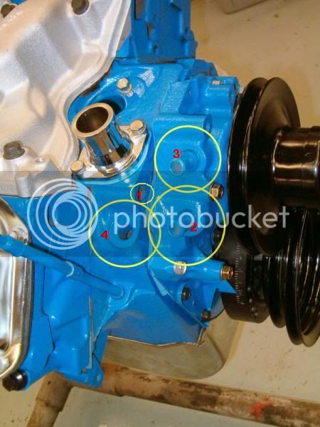
I was gawkin' at my engine this afternoon after I got the intake nailed down and noticed, "I have what appears to be 3 water passages." (circled below)

wtf.jpg

So, my question is: What do I do now? Do I block off the obvious extra port in the "late model" water pump (I'm thinkin' 351M)? Or just go get another [correct] water pump (with a single heater hose outlet/inlet)?

I wish there was a 'bang head against the wall' emoticon, but for now I'll just live with these: :shrug2: :huh: rofl

 
Last edited by a moderator:
Man that sucks. I'd bang head on the wall too then get the right pump. I hate that...it's sooooo frustrating.

 
Man that sucks. I'd bang head on the wall too then get the right pump. I hate that...it's sooooo frustrating.
The easy answer is change the water pump. The circle to the left .... is that a temp plug placement hole...not a water passage?

 
Last edited by a moderator:
I believe the threaded hole in the front of the block below the thermostat is for the temp sender. Easiest is to move the fittings to where they belong and plug the extra hole with a brass pipe plug and some sealant. The aluminum pump I have has the same set-up. I cannot remember which hole on the pump gets plugged. I can look in the morning.

 
The easy answer is change the water pump. The circle to the left .... is that a temp plug placement hole...not a water passage?
You know - now I gotta wonder. I'm looking at the old pictures of when I pulled the engine, and I'm not sure. I only have a 3.2megapixel "beater" camera, and didn't really take a ton of reference pictures (like I should've). Even so, just about every picture of my engine before teardown seems to have that side hidden for one reason or another.

In this pic, it looks like there's some kind of 'spider' connection on one of the water pump outlets, as well as a plug on the one in the block (thinking temperature plug). But in the next pic, it shows one of the hoses going into the port in the block, and the other into the top port of the water pump.

44821_153296291347964_8126026_n.jpg


44734_153558691321724_3462638_n.jpg


This pic better shows the 'plug' in the 'block port' (well, barely, anyway) and still the 'spider thingie' on the lower water pump port.

46400_155084234502503_7449094_n.jpg


I'm stumped because obviously, there were two water pump ports on the original, even though I have no idea why. I'm leaning toward the 'temp probe/plug' idea... but I'm not sure.

Hopefully, someone with greater 351C-2V knowledge than I will be able to help sort it out. Thanks again, and keep the ideas coming!


I believe the threaded hole in the front of the block below the thermostat is for the temp sender. Easiest is to move the fittings to where they belong and plug the extra hole with a brass pipe plug and some sealant. The aluminum pump I have has the same set-up. I cannot remember which hole on the pump gets plugged. I can look in the morning.
OK - that answered one of my original questions to my pal Jim (about the temp sender) - thanks!

I'm thinking that 'spider thingie' on the lower water pump port was probably more of the previous owner's "Redneck Engineering" of a block-off 'cap' of some sort. But yeah - I'd be interested to know what you come up with Jeff. Thanks again!

 
Last edited by a moderator:
This is how my engine is set up.

wtf.jpg


1) coolant temp sensor

2) temperature controlled vacuum valve

3&4) heater hose

Here's the temperature controlled vacuum valve

100_4667.jpg


In your case I think if you were to block off #2 and run the heater hoses to 3 and 4 it would work. We'll see what droptop73 says.

 
Here is how mine is setup.

1. Heater send

2. Temp sensor

3. Plugged

4. Heater return

73waterouts.jpg


Last edited by a moderator:
On my 351 C 2v in my 70 Mach1, i also had a sensor of some sort in number 2 like TheJ. When i changed the water pump i got just one like yours, with 2 outlets/inlets on the pump. Ended up blocking number 2.

 
Mine is set-up exactly like Jayson's. #1 is temp sender, #2 plugged since I'm not using the vacuum switch and #3&4 heater hoses. I see #4 is missing the fitting. I have heard replacements are available from NAPA it is pressed in IIRC.

 
Last edited by a moderator:
OUTSTANDING!! So basically, "Get a temperature sender, find the 'hose nipple' for Number 4, and block off Number 2," since I don't have any emissions gear. I'm not 'restoring' this to factory specs, after all. And my pal Jim just remembered what the temperature controlled vacuum valve was for.

I'll still gladly consider any input regarding the temp controlled vacuum valve though - if there's more to it than just the emissions equipment. I'm not anywhere close to making a hard decision or anything. It just made me start thinking yesterday when I saw that.

Thanks for jumping in on this guys - just one more example of what an awesome resource this place has become.

 
Basically is switches the source of vacuum to the distributor. On cold starts the distributor gets manifold vacuum and when it warms up it gets carb vacuum.

 
Interesting, J. Thanks for the info. I'll hafta re-think just blocking it off then.

Jeff - appreciate you're checking on your car... and good info about NAPA. I'll check with them because I'm pretty sure I lost that fitting last year when I tore the engine down.

 
This is how my engine is set up.

wtf.jpg


1) coolant temp sensor

2) temperature controlled vacuum valve

3&4) heater hose

Here's the temperature controlled vacuum valve

100_4667.jpg


In your case I think if you were to block off #2 and run the heater hoses to 3 and 4 it would work. We'll see what droptop73 says.
TheJ ID of the holes is correct. Hole 2 is for the ported vacuum switch used with a dual diaphragm distributor if the engine begins to overheat (usually at idle) the heat sensitive vacuum switch removes vacuum from the retard side of the distributor diaphragm causing the timing to advance, increasing engine and fan speed, and cool the engine down. Holes 1 and 2 should be threaded. If you have a good OEM temp sender use it. I haven't found one in the last 15 years that has the correct resistance range (causes the gauge to be wrong, usually high). Chuck

 
Thanks for weighing in, Doc & Chuck! I swung by NAPA earlier and picked up the correct temp sensor for #1 and fitting for #4. Gonna hafta come up with a cap/block off for #2 now since I'm going aftermarket [Pertronix Flame Thrower] with the distributor.

wtf.jpg


Back
Top