


nursieee
Well-known member
- Joined
- Dec 8, 2019
- Messages
- 68
- Reaction score
- 2
- Location
- Sweden
- My Car
- Ford Mustang Fastback Mach 1 1973
Trying to understand if this is right.
First is the battery, then are there the starter solenoid. On the first pin of the solenid there is + from battery going in
and a Yellow or yellow black cable(hard to see the color) which goes to the alternator regulator (marked with y)
and there is also i cable connected to a short stop 12v 40A (dont see this one in the wiring diagram). (marked from +)
From the second pin of the short stop there is red-orange cable (marked r-o) that goes all the way to the alternator gauge? Which never did work. Should it be wired like that?
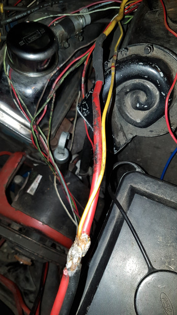
And there is also black thick cable from the second pin of short stop (marked 1) and the red thick one (marked 2, if you follow the arrow direction you end up in the alternator) if you follow it the other way you find that those to thick cables, red and black are soldered together to two 10 inch stubs, one thin yellow and one thick red (see picture 2) and they are spliced to one thin yellow and one thick yellow and those 2 goes trough the firewall. What is this or how should it be?
(For now i also have to bypass the shortstop with a cable otherwise the car dont start so it seems broken.)
Anyone who can explain this to me or tell me how it should be?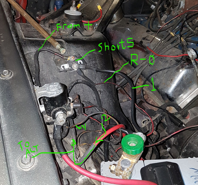
the red cable seems to come from the alternator (its the one marked with 2 on pic 1)and the black from pin 2 on the short stop(marked 1)
So the easy question is, what do i do?
First is the battery, then are there the starter solenoid. On the first pin of the solenid there is + from battery going in
and a Yellow or yellow black cable(hard to see the color) which goes to the alternator regulator (marked with y)
and there is also i cable connected to a short stop 12v 40A (dont see this one in the wiring diagram). (marked from +)
From the second pin of the short stop there is red-orange cable (marked r-o) that goes all the way to the alternator gauge? Which never did work. Should it be wired like that?
And there is also black thick cable from the second pin of short stop (marked 1) and the red thick one (marked 2, if you follow the arrow direction you end up in the alternator) if you follow it the other way you find that those to thick cables, red and black are soldered together to two 10 inch stubs, one thin yellow and one thick red (see picture 2) and they are spliced to one thin yellow and one thick yellow and those 2 goes trough the firewall. What is this or how should it be?
(For now i also have to bypass the shortstop with a cable otherwise the car dont start so it seems broken.)
Anyone who can explain this to me or tell me how it should be?
the red cable seems to come from the alternator (its the one marked with 2 on pic 1)and the black from pin 2 on the short stop(marked 1)
So the easy question is, what do i do?
")