Vacuum hose routing

7173Mustangs.com

Help Support 7173Mustangs.com:

This site may earn a commission from merchant affiliate links, including eBay, Amazon, and others.
Joined
Jun 14, 2019
Messages
551
Reaction score
164
Location
Coachella Valley (Palm Springs)
My Car
1973 Convertible, 351 4v CJ, C6, Mach 1 Decor options, power: steering, brakes and windows, a/c, Rally Pac gauges, Deluxe interior.
[url=https://ibb.co/ZVjjKXW][img]https://i.ibb.co/zrMMbxG/s-l1600-2.jpg[/img][/url]
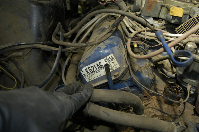
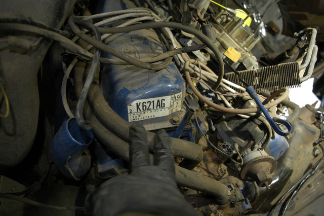
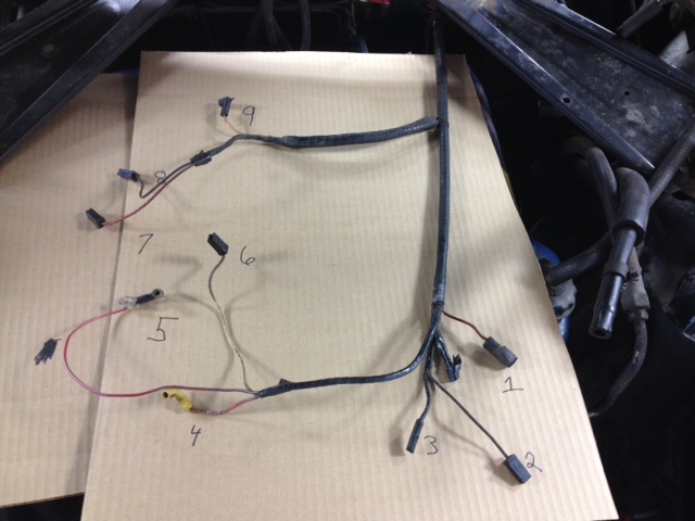
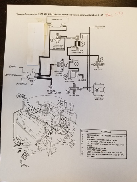
I swear I've read every (and there are MANY) posts related to vacuum hoses, and I've reviewed each and every diagram.  I still can not find a diagram to match my configuration:  '73 351 4V automatic and a/c.  I tagged every hose going to or from the PVS and TCV valves before sending the engine out, but when I got it back from the machine shop:  a few hoses misplaced and none were still tagged, so I'm having to figure it out.

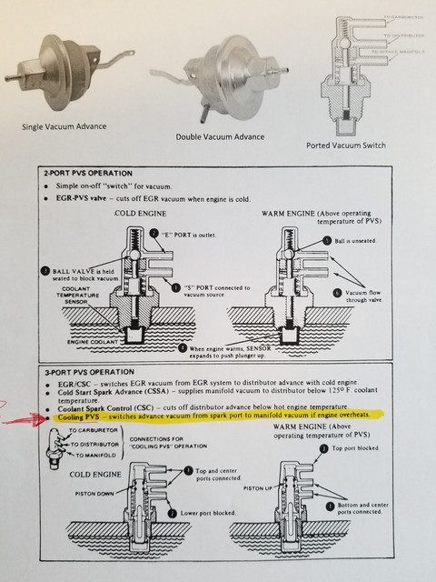
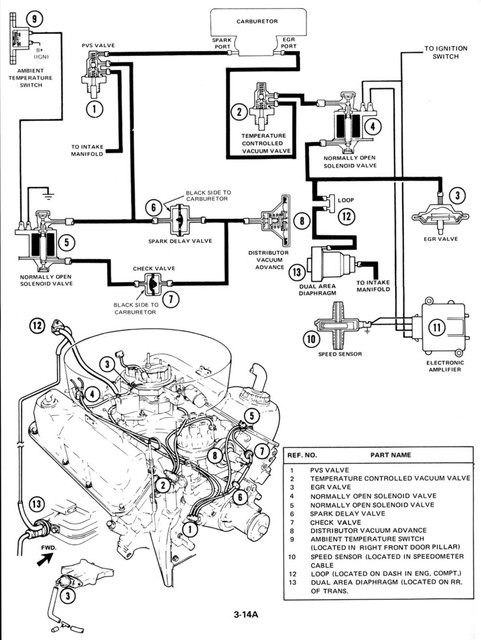
There are diagrams for a 351-4v w a/c and auto, but they don't match what I have under the hood.  Referencing the Ford Shop Manual diagrams posted by DonC for example, I should find my config in 3-14A (attached).  Thing is... I can not find the normally open solenoid valve marked #5 (for PVS valve outlet #2 and the distributor vacuum advance).  I'm assuming it's the same sort of valve as the normally open solenoid valve marked #4 (which is there on my engine and matches the diagram's location) but where the heck is #5?  Under/behind what?  The other thing is, a solenoid valve will have wires and I have no wiring unaccounted for so I just don't think I have the valve indicated as #5 or at least not in the location indicated for #5.  If there is no #5, is the correct routing a direct hose from PVS port 2 to the vacuum diaphragm?

None of my existing hoses have any of the check valves indicated in the diagram (should I be concerned?)  And another thing... the firewall mounted loop (#12 in the diagram) in my car is actually 4 ports.  Not sure that matters to this discussion.

Onward, onward, onward...


Will have to find it but I have a copy of the Osborn Factory assembly manual that Ford used. The pictures are so light in the manual it is difficult to see when in hand. I will look when in garage this afternoon. Going to sit in workroom and deer hunt this afternoon. I got two last year. I have a 4,000 sq. ft. hunting stand, lol.

What was DSO for your car. I think California was different will not swear. Do you have the sticker that was on the valve cover I think it also tells the calibration and set up of your engine. Here is pic of the sticker. This is a Charlotte, NC DSO code engine.


pic host

 
Was built at Dearborn, first sale in Long Beach so CA emissions I 'spose. My tag reads KK620AG ("2" is behind the pipe)


Last edited by a moderator:
Found this as fordification.net -- fascinating site.  Factory made for California (KK) non-air pump egr engine 620 (Q code; 351-4V) Revision A with Air Conditioning.


Last edited by a moderator:
RC92234,

Looking at the pic of the valve cover you posted, looks like you may want to look at diagram 3-16A.

Here is a link to a previous post that has some vac diagrams for 71-73.

https://www.7173mustangs.com/thread-vacuum-hose-diagrams?pid=246021#pid246021

3-16A does not show using valve #5 for a 73-351-4bbl-AT. Doesn't show any of the check valves or an ambient temp switch either, but your engine feed harness should have 2 additional wires branched off with the oil pressure lead to connect valve #4. I have pics of a feed and the harness that shows items 10 and 11 if you need.

As far as the loop(s) on the firewall, is it possible you have a part that has 2 - 2 post loops in a single piece? Have attached pic that was taken off another post on this site.


Curious now. Do you still have items 10 and 11 installed? Never seen those in real life with the 2 piece spedo cable. If not installed, then valve #4 may not matter?
Starting with the last question (10 and 11 installed?) I will have to look and see.  Those parts aren't under the hood.

The problem with 3-16A is the temperature control valve shown only has two ports; mine has 3.

And yes, the four-port loop is actually two-loops formed together (but not cross linked).  

If you send me the pic of the harness, I'll check.  Thanks!

EDIT: Goodness... I think I misspoke about the temperature control valve. I do have the 2-port temperature control valve installed in the heater hose. I *also* have a PVS valve installed in the water pump. It's the routing from the PVS that is giving me the woe.

 
Last edited by a moderator:
I have always been a bit confused over the combinations of harnesses and vacuum lines and parts. So not sure if any of this will help.

I use config 3-15A as I have a 351c-4bbl-MT. Only got into the vacuum/emissions stuff because I wanted to know why I had leads on my feed harness that went to nothing. Seems a harness could fit several configurations.

I only have the 2-port PVS in my setup but it is not on the water pump. It is inline with the heater hose. Original Ford part. 

Pics attached. My understanding is/was that when the configuration required both 2 and 3 port PVS's, there was no place to put the second PVS as the 351-c water pump only had threaded holes for 1? Guess the heater hose idea stuck on other configurations. Could be what you need.


The harness Pics are not mine. Again, taken from other posts. Looks like a feed harness for 3-14A. I believe # 7-8 (Brown and Red/Yellow) are for the rear valve and 9 is oil pressure. #2 would have gone to the valve on the left front if needed. My harness has a red lead with up front by #2 and nothing extra back with the oil pressure switch. Almost like they planned on putting a valve in the front?? (More confusion for me...) Don't have that Pic handy, but can find it if you want to see it. 

Note the single wire in the last Pic that has something to do with the valves and comes through the firewall high up and near center. Think the rest is tucked in near the left kick panel and then goes speed sensor and??????

image-1.jpg
Under-Hood-Harness.jpg


Last edited by a moderator:
Does anybody have this harness and could verify the wire colors and where the wires go?

1.  #369 brn/ora hash to spark delay valve bypass solenoid

2.  # 57 bla to spark delay valve bypass solenoid

3.  ?

4.  #16 red/lt. grn stripe to coil +

5.  #39 red/whi stripe to water temperature sensor

6.  #4 whi/bla stripe to choke

7.  #640 red/yel hash to egr cutout solenoid

8.  #81 brn/yel dot to egr cutout solenoid

9.  #31 whi/red stripe to oil pressure sensor


I have always been a bit confused over the combinations of harnesses and vacuum lines and parts. So not sure if any of this will help.

I use config 3-15A as I have a 351c-4bbl-MT. Only got into the vacuum/emissions stuff because I wanted to know why I had leads on my feed harness that went to nothing. Seems a harness could fit several configurations.

I only have the 2-port PVS in my setup but it is not on the water pump. It is inline with the heater hose. Original Ford part. 

Pics attached. My understanding is/was that when the configuration required both 2 and 3 port PVS's, there was no place to put the second PVS as the 351-c water pump only had 2 threaded holes, 1 for a 3 port PVS and one for the temp sender. Guess the heater hose idea stuck on other configurations. Could be what you need.


The harness Pics are not mine. Again, taken from other posts. Looks like a feed harness for 3-14A. I believe # 7-8 (Brown and Red/Yellow) are for the rear valve and 9 is oil pressure. #2 would have gone to the valve on the left front if needed. My harness has a red lead with up front by #2 and nothing extra back with the oil pressure switch. Almost like they planned on putting a valve in the front?? (More confusion for me...) Don't have that Pic handy, but can find it if you want to see it. 

Note the single wire in the last Pic that has something to do with the valves and comes through the firewall high up and near center. Think the rest is tucked in near the left kick panel and then goes speed sensor and??????

image-1.jpg
Under-Hood-Harness.jpg
The 2-port valve in the heater hose is a temperature control valve, not a PVS as is mounted in the water pump.  Check the manual again - that's what's in shown in configuration 3-15A.  I do have the tcv in the heater hose, but also the PVS in the water pump.  And my configuration doesn't use a distributor vacuum advance control (#17 for 3-15A); that location has a solenoid.

 
I stand corrected. Happens too often. The diagrams I have do name the 2 port unit as a Temp Control Vac Valve and not a PVS. You are also correct that with my having a Manual Transmission, I do not use/have either of the solenoid valves, but use the DVAC (#17 for 3-15A).

A pic that may help, but from a 351c-2V and not a 4V. (#5 for 3-14A config mounted on the valve cover). Note that Vac lines showing are not correct and simply looped around.

JUST READ YOUR EDIT-----------

Being you have a Q code, is it possible that you should use config 3-16A and not have/need a PVS or the #5 sol. valve, Etc.? Your valve cover decal pic shows 16A in the upper right corner. Maybe earlier in it's life the PVS was added to plug the threaded hole in the water pump? I have a plug in mine.


Last edited by a moderator:
Does anybody have this harness and could verify the wire colors and where the wires go?

1.  #369 brn/ora hash to spark delay valve bypass solenoid

2.  # 57 bla to spark delay valve bypass solenoid

3.  ?

4.  #16 red/lt. grn stripe to coil +

5.  #39 red/whi stripe to water temperature sensor

6.  #4 whi/bla stripe to choke

7.  #640 red/yel hash to egr cutout solenoid

8.  #81 brn/yel dot to egr cutout solenoid

9.  #31 whi/red stripe to oil pressure sensor


I do not have this exact harness. Mine is a bit different but I use this pic for a reference of sorts. I do not have wires 7 and 8, but have an additional Red wire grouped up with 1 th 3. I believe this one shown is for a 73-351C-2V-Auto and a lot depends on the connections on the other end.

If I read the schematics correctly, which can be a bit shaky, for this harness you nailed #4 th 9.

I see #1 th 3 as:

1.  #640 - Red/Yellow to throttle position solenoid.

2.  #369 - Brown/Orange to solenoid valve. (Dependent on engine)

3.  #347 - Black/Yellow - A.C. Clutch


*Note - #57-Black should be a short ground lead that is not part of the harness but runs from the solenoid valve to the valve cover bolt.
 
Last edited by a moderator:
Can it be that simple??? The code on the valve tag points to the page in the manual? But if so, it *really* adds to the confusion as the car when I got it (and it was running) the PVS was there and all the vacuum hoses placed. The 16-A configuration in the manual is nothing like what I have in the car and, it would leave the vacuum port in the manifold completely open; that can't be right.

(The backstory you don't know: I broke some bolts replacing the water pump and had to send the engine to a machine shop for repair. I had tagged all the vacuum hoses, but when the engine came back the tags were gone and the hoses were in weird places. Now I'm trying to reconstruct. I thought I'd taken pictures of everything I needed *before*, but dagnabbit, I just didn't think to get the COMPLETE routing of each vacuum hose. D'oh!)

 
Not saying for sure....but it might be just that simple, but a lot of what I think I know can quickly turn into what I thought I knew.

Never can tell what a previous owner may have done. Carb changes, distributor changes, Etc. can easily change things. Lots of folks took the evil emission stuff off and threw it away.

It is also a California car (KK on the tag?) but I think the 16A config/calibration still stands.

You said you had all the wires accounted for so I assume there is no wire (Brown/Orange) up front for the infamous valve #5 from 3-14A.....did you ever have that solenoid valve?

Not sure which vacuum port on the manifold you are mentioning. Is it the one in front of the carb, or the "tree" in the rear? Lots of other hoses on the tree, Brake Booster, Air Cleaner Flapper, Etc. What isn't used on the tree gets a rubber cap. You may or may not have the one in the front.

Gotta ask. Are you running a single or dual vac distributor? Do you still have the dual vacuum modulator on the transmission? Is this the original engine/trans to the car? 

And trust me, lots of pictures before taking something apart....ask me how I know.
16-A just can't be correct; it doesn't have a PVS port coming off the water pump.  The manifold vacuum port is a nipple right in the manifold -- nothing else attached there -- in front of and to the left of the carburetor.  Mine is the opposite side where shown in the 14-A diagram. The carb (Holley 4300D) also has one port, pretty much where 14-A shows one, but I don't know if it's the EGR or Spark port (per the diagrams).

I've been assuming I have a single vac since the only port on the distributor there is via the advance diaphragm. It's an old, old cap with a rotor and points so I'm fairly sure it's original.  As to original engine/trans for the car, the valve cover build date matches the Marti report and I'd need to check casting numbers and whatnot to truly verify, but it's the engine that came with the car when I got it (in June) and it ran then -- that's as correct as I'm trying to get back to.  And no, there is no stray plug for the solenoid in 14-A, so I don't think this car ever had it.

But thanks for mentioning the vacuum port tree on the rear of the manifold. It's currently "full" but I've been wondering where the air cleaner flapper connected since it's been so long since I took it off.

 
Sounds like you have a very original car to start with. Always a good thing. Can only assume that if parts were there, they were there for a reason. I don't have a lot more to offer, but....

Went back to the beginning of this post and re-read that you have AC. Missed that originally. I never had AC so didn't give it a thought. Perhaps the reason for the 3 port valve? Nothing to do with emissions?

Came across this today. Old post discussing the DVCV and how it relates to Idle, AC and other loads, and Temp.

Worth the read, good information from others. Explains the need for the 3 port valve.

https://www.7173mustangs.com/thread-under-the-hood-mysteries-distributor-vaccum-control-valve?highlight=ported+vacuum+switch


Please keep in mind this is a wild guess on my part. Others please correct this as needed.

Perhaps it was like this? Added the 3 port valve to your calibration 3-16A? You did say you only had the 1 port on the carb and 1 on the dizzy?


Sorry, but to add to the confusion, there is this that shows the use of all 4 ports on the firewall for the Auto Trans.

 
Sounds like you have a very original car to start with. Always a good thing. Can only assume that if parts were there, they were there for a reason. I don't have a lot more to offer, but....

Went back to the beginning of this post and re-read that you have AC. Missed that originally. I never had AC so didn't give it a thought. Perhaps the reason for the 3 port valve? Nothing to do with emissions?

Came across this today. Old post discussing the DVCV and how it relates to Idle, AC and other loads, and Temp.

Worth the read, good information from others. Explains the need for the 3 port valve.

https://www.7173mustangs.com/thread-under-the-hood-mysteries-distributor-vaccum-control-valve?highlight=ported+vacuum+switch


Please keep in mind this is a wild guess on my part. Others please correct this as needed.

Perhaps it was like this? Added the 3 port valve to your calibration 3-16A? You did say you only had the 1 port on the carb and 1 on the dizzy?

Very interesting... I’ll have to give this a few minutes to ponder. But yes, one port on the carb and a single vac diaphragm.

 
Very interesting... I’ll have to give this a few minutes to ponder. But yes, one port on the carb and a single vac diaphragm.
Add what you drew and it absolutely makes sense, and seems rather straightforward.  I'll consider it the working option for now. Looking at the 16-A modified diagram, my air cleaner is different.  Mine is more like this, which is 3-11E for a 302 w a/c. There's enough else different that this certainly isn't my engine; but it is the air cleaner. I got a lead for yet another set of diagrams, so I'll see where that goes.

Back to the wiring - I concur with the other post where they say the brown/orange stripe is for the a/c clutch.


Last edited by a moderator:
Sounds like you are on your way. Agree about the air cleaner. Lines run from the flapper on the snorkel, through the bi-metal, and finish off at the tree in the rear. Manifold vac for the 3 port should connect to the intake manifold single port at the front? If your other source provides the definitive answers please post. Would love to see if I was even close.

Great source for 1973 wiring is here under the Mustang Data drop-down/Wiring Diagrams. Grid F-78 for the AC (#347-Black/Yellow Hash). Grid E-88 for the sol valve used on the 351-2bbl (#347-Brown/Orange Hash)

*Note* I believe I misspoke earlier about 351C water pump. It does not have temp sensor in it. It is located elsewhere.

 
Back
Top