Dash Reassembly -

7173Mustangs.com

Help Support 7173Mustangs.com:

This site may earn a commission from merchant affiliate links, including eBay, Amazon, and others.

GrantOv

Well-known member
Joined
Feb 5, 2024
Messages
128
Reaction score
46
Location
minnesota
My Car
1972 Mustang Mach1
I'm starting to piece back my dash. It may be a few weeks as I haven't got my gauges back yet but but still quite a few things I can do in the meantime.

A couple questions I could use some help with -
1) For the center bezel air vent it could fit either way and I'm not sure which way it should be. Either with the angle down or vice versa? See pic of where I have the long or tall side towards the top.

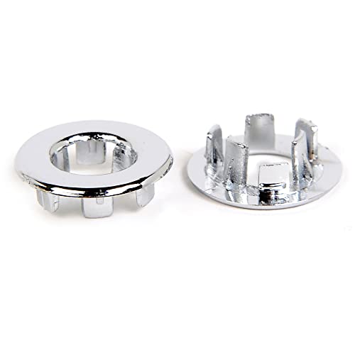
2) To reattach a new glove box bezel I believe I need to use pressed nuts. The diameter of the plastic stud is approx 3/8". But trying the 1/2" pressed nut seems to tight. First off, are pressed nuts what is recommended for this panel? And if so, what size and where to find them as they are sort of a nonstandard item. The 1/2" is just a bit too tight for my comfort so one thought is that I could hone them out a bit with a bolt or thread cutter?? Thoughts on next steps?

Thanks!
 

Attachments

  • PXL_20250201_225055813.jpg
    PXL_20250201_225055813.jpg
    675.8 KB
  • PXL_20250201_213104244.jpg
    PXL_20250201_213104244.jpg
    437.2 KB
Last edited:
On #2- that has been an issue with the repop deluxe dash panels forever. The posts are oversize. I couldn’t find the post, but I think I bought different hex speed nuts from McMaster Carr that were slightly larger.

Edit… see my post below. Looks like on my repop the posts were smaller than OEM.
 
Last edited:
Thinking about this a bit longer - perhaps something like this may be the ticket? The first is called a push on fastener and likely are difficult to remove. The second is a speed nut which I think is what Bentworker was referring to from McMaster Carr. Anyone else use these on the aftermarket dash panels?
 

Attachments

  • push fastener.JPG
    push fastener.JPG
    64.8 KB
  • nut.JPG
    nut.JPG
    21.3 KB
On #1, you want the longer side on the bottom. It looks like yours is upside down. Here's a picture of what it should look like from the back side installed.

On #2, the original Stamped Nuts that fit your original bezel are available from AMK products. I don't know about variances on the reproduction sizes, because I reused my original. But if you want to try 4 new nuts here's a link:

https://www.amkproducts.com/bulk-fasteners-products/?Product_ID=12965
 

Attachments

  • Center Vent.jpg
    Center Vent.jpg
    1.9 MB
Thanks again for the tips and links!

A couple ore things I ran into today that may be obvious to someone that has done this recently.

(1) I was reinstalling my AC/Heat controller and noticed that it does not fit in the opening cleanly. The unit has a surface that a person would think would fit in the opening but its about 1/8 larger than either my new radio/heater bezel or my old one. Maybe that is just the way its supposed to be?

(2) Does anyone have a picture of how the floor convenience lamp units are mounted? I assume one of the holes under the dash are meant for it but not sure which one etc., Also - since the lamp ground is through the connection I assume we should make sure the bolted connection to the dash and from dash to car are making a clean connection. I'm not sure what else is counting on the dash for the ground path return.

(3) I am baffled at how the long skinny trim piece is actually supposed to be mounted. The holes line up with either instrument or glovebox side somewhat but the shape fits neither as a trim piece. What am I missing here?

Thanks!
 

Attachments

  • PXL_20250202_144342379.MP.jpg
    PXL_20250202_144342379.MP.jpg
    544.2 KB
  • PXL_20250202_151049755.jpg
    PXL_20250202_151049755.jpg
    363 KB
Thanks again for the tips and links!

A couple ore things I ran into today that may be obvious to someone that has done this recently.

(1) I was reinstalling my AC/Heat controller and noticed that it does not fit in the opening cleanly. The unit has a surface that a person would think would fit in the opening but its about 1/8 larger than either my new radio/heater bezel or my old one. Maybe that is just the way its supposed to be?

(2) Does anyone have a picture of how the floor convenience lamp units are mounted? I assume one of the holes under the dash are meant for it but not sure which one etc., Also - since the lamp ground is through the connection I assume we should make sure the bolted connection to the dash and from dash to car are making a clean connection. I'm not sure what else is counting on the dash for the ground path return.

(3) I am baffled at how the long skinny trim piece is actually supposed to be mounted. The holes line up with either instrument or glovebox side somewhat but the shape fits neither as a trim piece. What am I missing here?

Thanks!
1-Your AC/Heat controller face sits behind your Radio/Heater Bezel. You're right, this is the way it's supposed to be. I like your new Radio Bezel...nice upgrade

2-Here's a picture of my courtesy lamps mounted on my dash on each side. I did like you said and scraped some paint away where the bolt attaches.

3-If you plan to reinstall your Deluxe Bezel above your glove box, you can't fit that long skinny trim piece in. It's already molded into the top edge of your Deluxe Bezel panel in your picture. I think that skinny trim piece is for dash panels that don't have the big Deluxe Bezel, but just the painted metal dash. So you have both methods to trim the gap between the dash panel and the dash pad. I'm attaching a couple of diagrams that might help you see how it's all mounted.
 

Attachments

  • Instrument Panel Dash Pad Mount.pdf
    104.6 KB
  • Center Trim-Glove Area Bezel.pdf
    1.2 MB
  • Courtesy Lamp-Right.jpg
    Courtesy Lamp-Right.jpg
    588.5 KB
  • Courtesy Lamp-Left.jpg
    Courtesy Lamp-Left.jpg
    727.6 KB
Perfect - I understand now regarding the skinny trim piece. Thanks for the mounting pictures. I'll make sure to scrape off a little paint on the main dash mounting bolts also.

I ended up color matching my dash to the exterior - I'm really happy with the way that looks. Very cool to see it coming together again.
 
My reassembly for my dash is in full swing now. I was inspired by Moderator73 dash and had my dash painted to matched to my exterior by my local paint shop. I really like the way looks with the black deluxe panels. I'm going to put in all green LED's so that will look cool in my opinion.

Here are a couple pictures of progress. Thanks to the tip to just file down some pressed nuts from the local store to fit the glove box plastic studs. New ones come in at a little over 7mm, while the studs are 8.2mm. It didn't take long to get hone them out to 7.8mm which gave them enough cut to hold.

I have three questions in my harness that obviously I which I had taken more pictures of. I'm waiting on my gauges to be returned from RCC so perhaps 1 of them will be obvious when I get them back.

A - easy one - I assume this ground was meant to go somewhere specific on the dash frame but I'm not sure where it was attached. Maybe it just doesn't matter and I just find a hold to reuse.
B - this is right by the instrument cluster and I can't remember what it was meant to connect to. It will probably be obvious when the cluster goes back in.
C - I'm still baffled by this connector. It is by the R and L door along with the door switches but not sure where they were meant to connect to.

I did end up finding a map light for my center bezel - there didn't appear to be connector for it in my harness oddly so I was going to repurpose the center floor console since I plan to not have one. My issue is that I probably need about a 18in extension. What are the automotive plugs called in picture (D) that I could buy and build up an extension?

Next up; instrumentation cluster, center gauges and bezel and testing out the lighting with some 12V.
Cheers!

Grant
 

Attachments

  • PXL_20250209_193940637.jpg
    PXL_20250209_193940637.jpg
    523 KB
  • PXL_20250209_193948983.jpg
    PXL_20250209_193948983.jpg
    695.8 KB
  • PXL_20250209_201046460 B.JPG
    PXL_20250209_201046460 B.JPG
    293.9 KB
  • PXL_20250209_201024599 B.JPG
    PXL_20250209_201024599 B.JPG
    474.1 KB
  • PXL_20250209_201006064 B.JPG
    PXL_20250209_201006064 B.JPG
    401 KB
  • Plug b.JPG
    Plug b.JPG
    41.3 KB
A. No need to run a ground wire to the dash: it's part of the dash cluster connector and circuit card. I believe that may go to the relay metal panel or a metal portion of the behind-the-dash.
B is your tach plug
C is for the optional seat belt or seat latch system.
 
Hey Grant, you're dash is looking great! Midlife/Randy is a wealth of info and helps soooo much. On your "A" question, on the ground wire shown in your picture I've attached the Factory Assembly Manual page that shows the entire Instrument Panel Wiring harness routing. If you look at item #11 on the drawing, this is your double ground wire attaching screw. I added a picture of my ground attached at that point (see the Red arrow), and that's where it was when I first disassembled my dash.

On your "D" question, I have no idea what a connector like that would be called. Hopefully, someone more knowledgeable than me can help out on that one. But...as an idea in case you come up short in that pursuit, you might consider using Female/Male bullet connectors to make terminations that can plug into your harness. I've done this for my RetroSound radio to plug into my factory harness rather than splicing/hacking it up. It took a bit of trial and error to find the right SIZE bullet connectors that plug into our harness, but eventually stumbled on the right one. Here's a link from Ebay where I found they fit well.

https://www.ebay.com/itm/173614139361

Looking forward to seeing your cluster, center gauges and bezels, all in.
 

Attachments

  • Inst Panel Wiring Diagram.pdf
    1.7 MB
  • Dash Harness Ground Location.jpg
    Dash Harness Ground Location.jpg
    1.1 MB
  • Correct Bullet Size.jpg
    Correct Bullet Size.jpg
    1.8 MB
  • Bullet Connector Example.jpg
    Bullet Connector Example.jpg
    792.6 KB
Back
Top