New 351c Build.

7173Mustangs.com

Help Support 7173Mustangs.com:

This site may earn a commission from merchant affiliate links, including eBay, Amazon, and others.
Hi Barnett,

I h ad to go back through the post to see what everyone was on about.You are absolutely correct in the casting dates, I think he was using the engine number for a reference to come up with what vehicle the engine was out of. As for his comment about the 351 crankshafts, well he is a bit off there. Ford Australia started casting up their own cranks (both 302 and 351) as well as cylinder heads, conrods etc in early 1972. Ford Australia only had rough cast blocks sent over from late 71 and they started building all their own Cleveland engines from then on, with the exception of the 4V engines, they were still fully imported and only "M" code type engines. They ran out of imported 2V engines around mid 72, after that the Australian built 302 and 351 2V engines went into all Australian built vehicles. Hope that clears it up.

 
I received my Whydendorf lifter bushing kit yesterday.

http://www.wydendorfmachine.com/kitb.html?kitid=2

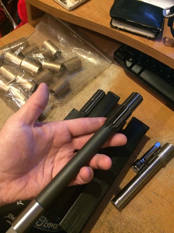
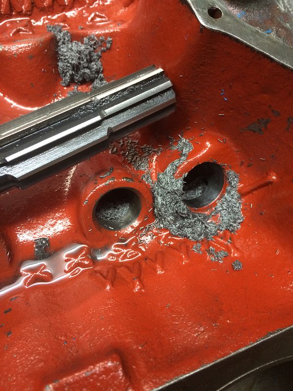
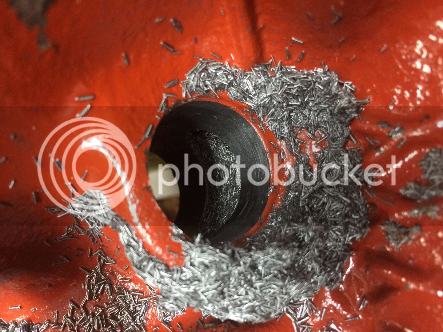
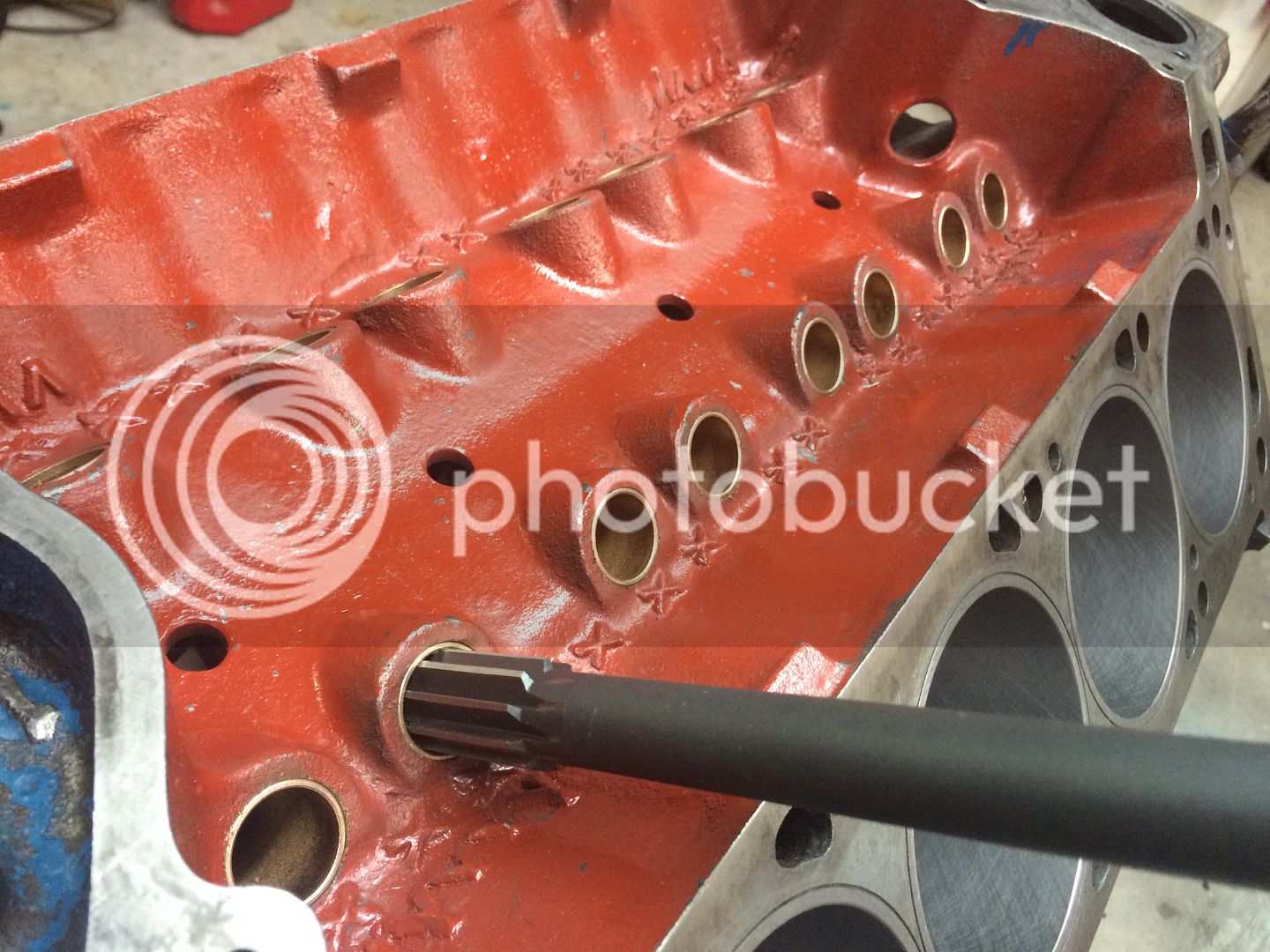
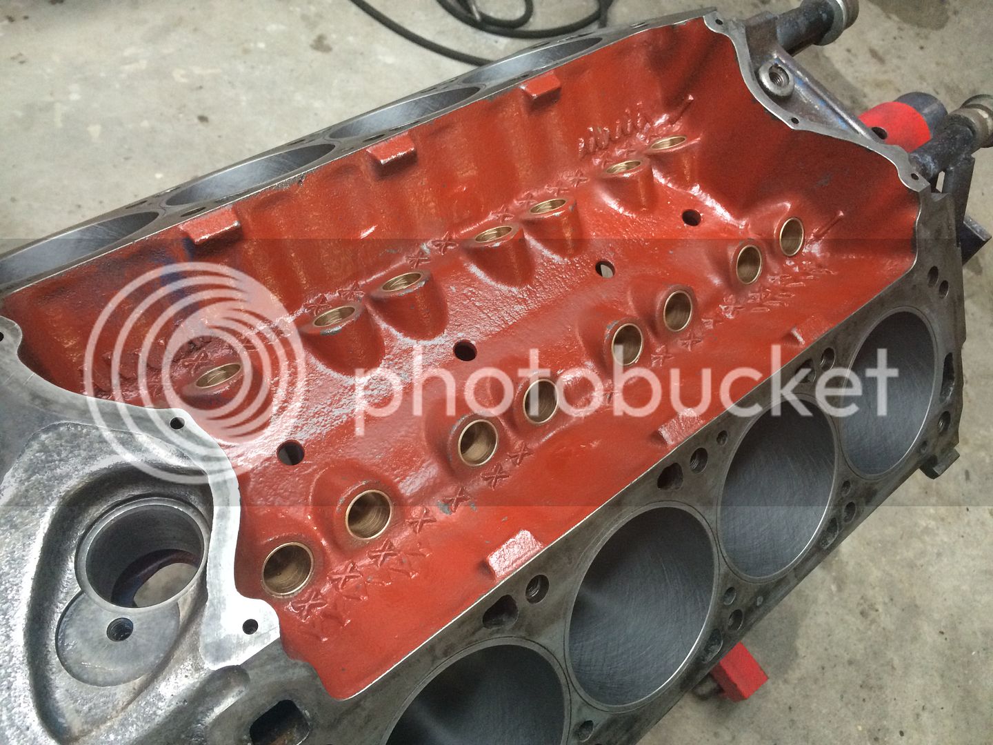
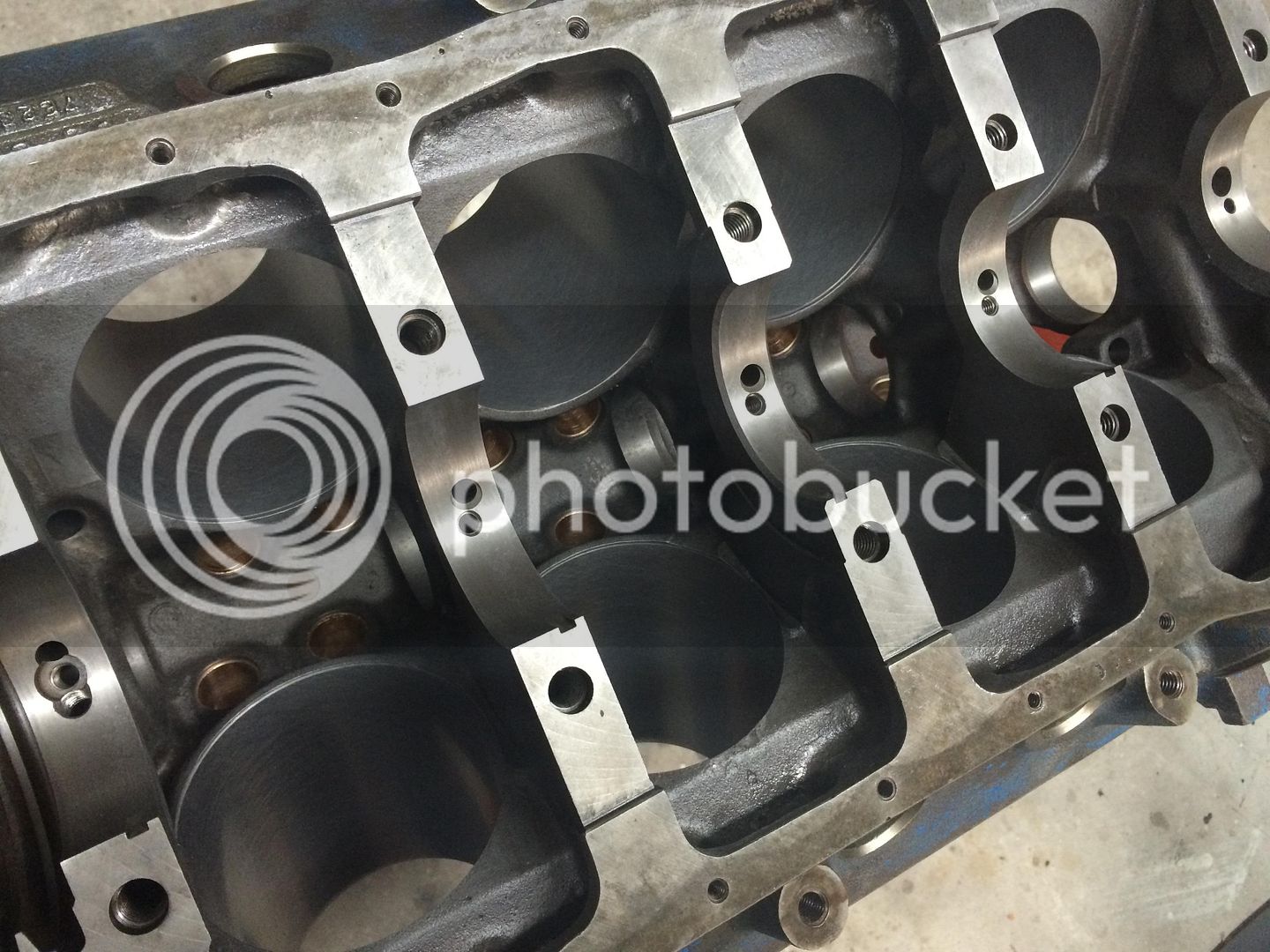
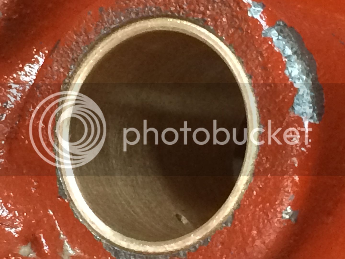
Took about 2:15 to ream out all 16 lifter bushing holes. A real workout for my drill and arms. I went through a whole big can of WD-40 during the process. It's not complicated. Just slow going. Many stops to lubricate and clean the reamer during the process of doing each lifter bore. I have much cleaning to do before driving in and reaming the bronze lifter bushings. Probably next weekend as I need to hang Christmas lights tomorrow.

IMG_2188_zpsa76a775b.jpg


IMG_2189_zps242f0b21.jpg


IMG_2190_zps885e8bb2.jpg
What size holes have you decided on to drill into the bushings? Chuck

 
.

you could really run a hole as large as 1/4" and still be fine.

.

 
What size holes have you decided on to drill into the bushings? Chuck
The instructions recommend a .043" hole. I'm going with a SFT cam so that should be fine. If it were hydraulic or a roller cam it might be necessary to drill a larger hole. I'd think a hole the same size as the one in the side of the lifter would be appropriate. Most are .125" or 1/8". That would allow maximum pump-up flow on cold starts.
Thanks. I was just curious. Chuck

 
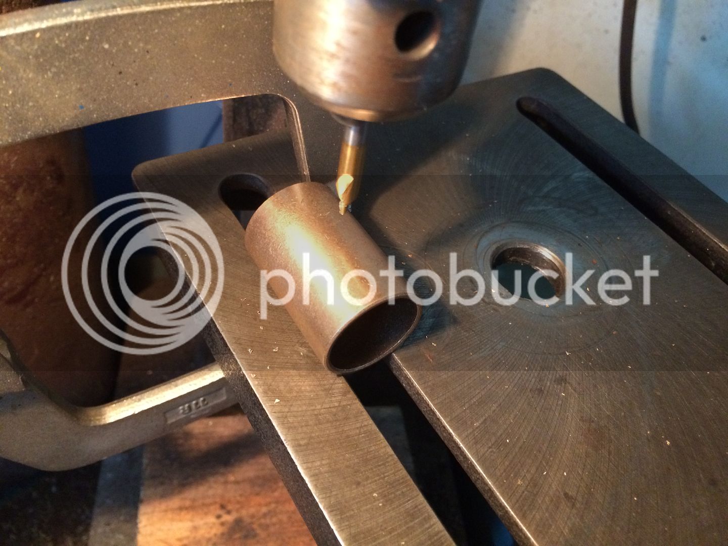
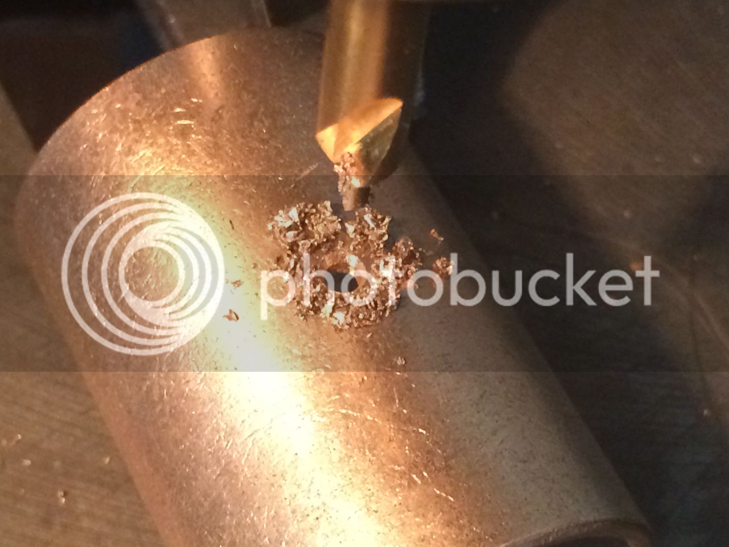
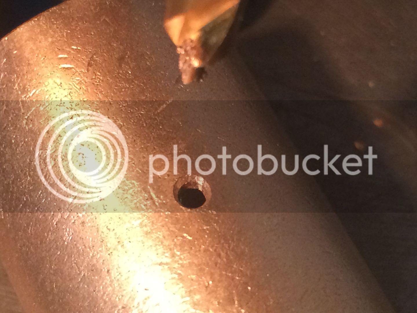
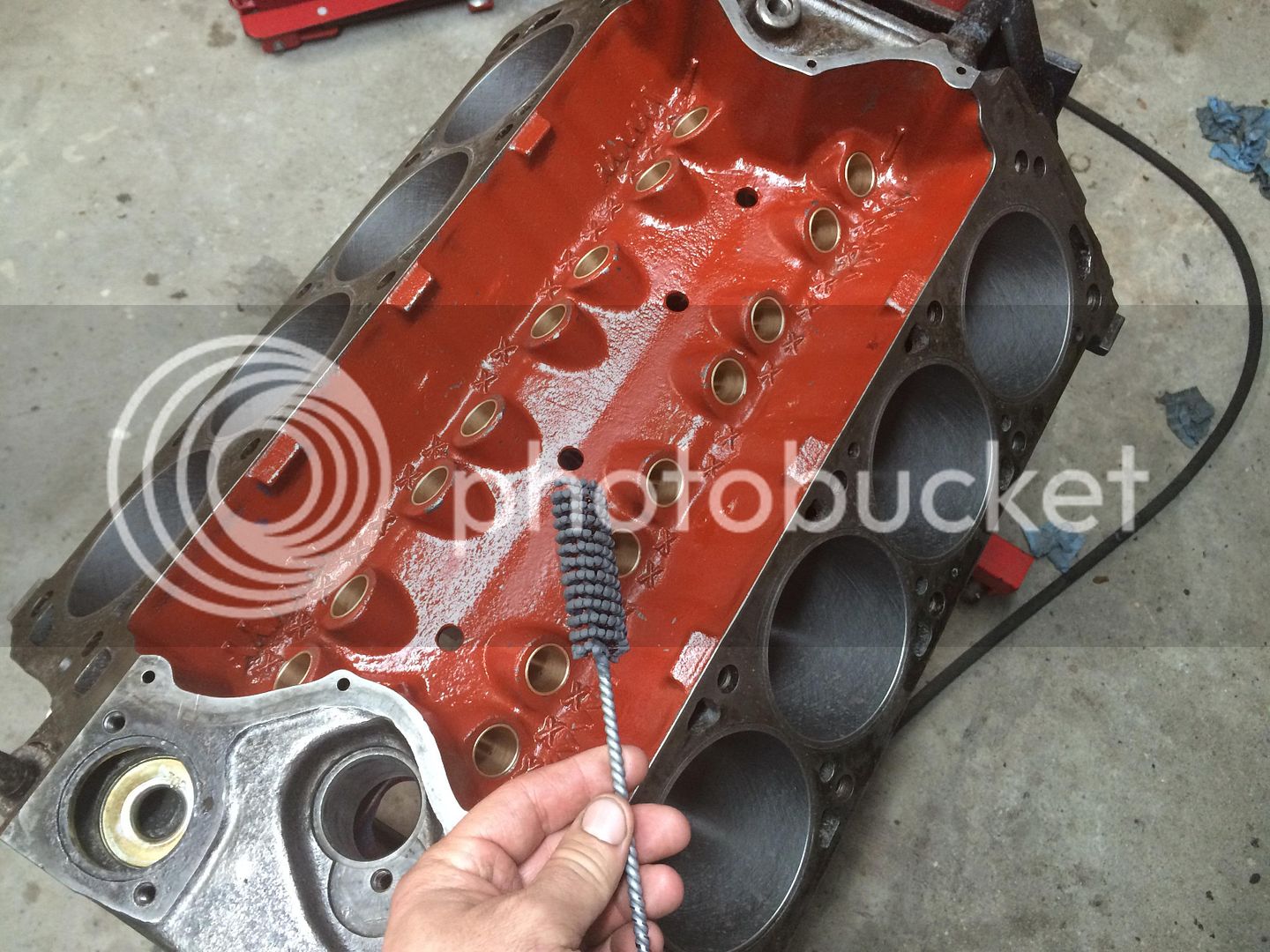
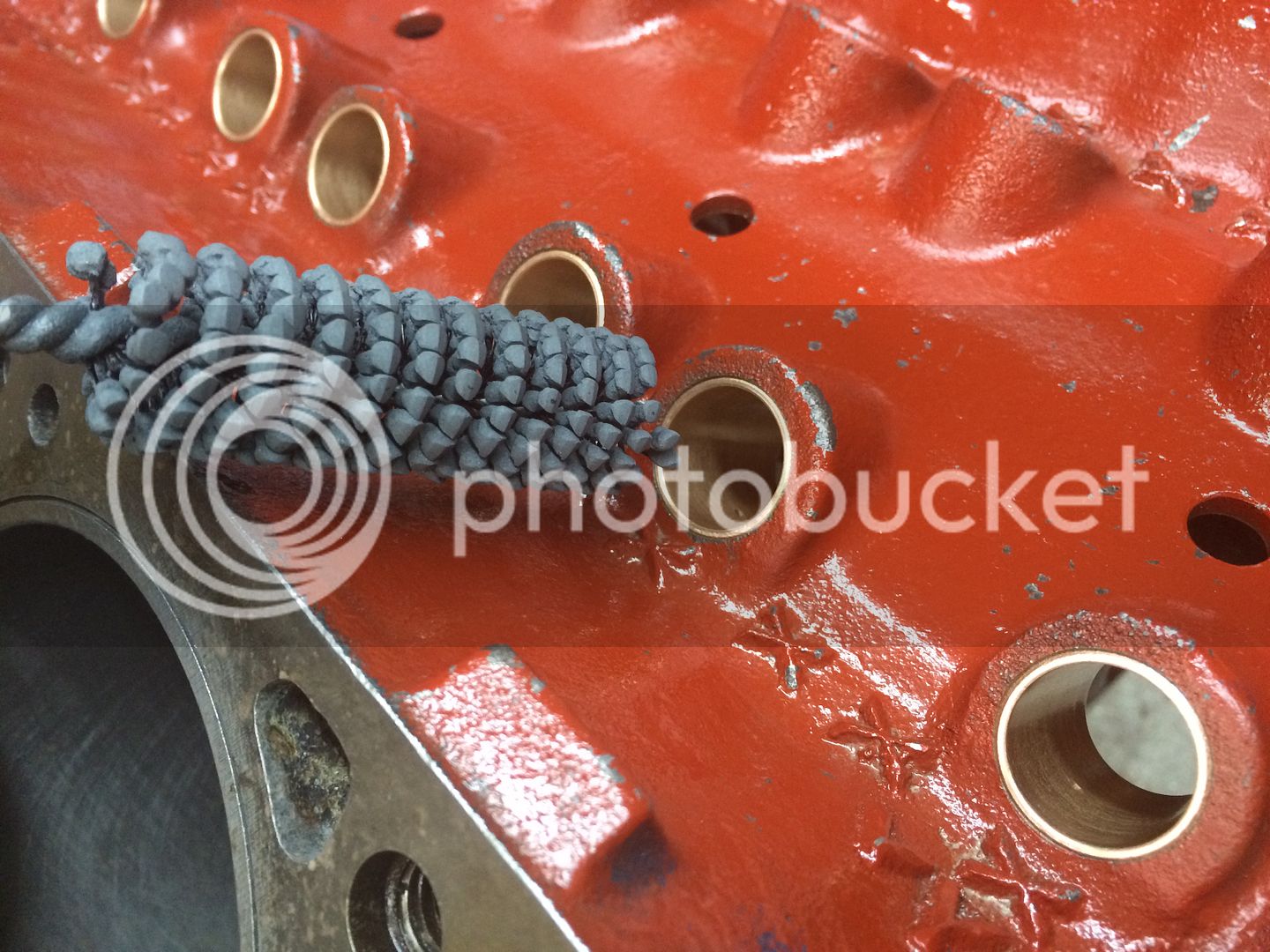
[attachment=28709][attachment=28709][attachment=28709][attachment=28709]Today I started by using my 400 grit flex hone and cleaned up the cylinder bores. Then I pulled it outside and started giving it a thorough clean from all the metal chips from reaming the lifter bores. After much drying and cleaning I turned my attention to drilling the oil holes in the lifter bushings. I settled on a .080" hole. I set up the drill press so I could knock out all 16 with ease and consistency. The piloted drill bit gave the hole a nice finish. I hammered in the bushings then reamed them to their final size. Unfortunately, the reamer ended up not being the correct diameter. The final diameter ended up being .8745" and the lifters are exactly .8745". They are a very tight fit. They do fit but I need to force them into the bushings and push quite hard with my thumb to get them to go all the way through the bore. Definitely too tight. I need to contact Whydendorf machine and see if they can exchange the reamer. Now it is a game of fractions of an inch to progress. With the holidays I don't expect this to get resolved until the following week after Christmas.

IMG_2201_zpsff4630bb.jpg


IMG_2202_zps4d8c41f6.jpg


IMG_2204_zpsc7ee7cd2.jpg


IMG_2210_zps9cc56885.jpg


IMG_2212_zps4701a6ad.jpg


IMG_2214_zps124898b7.jpg


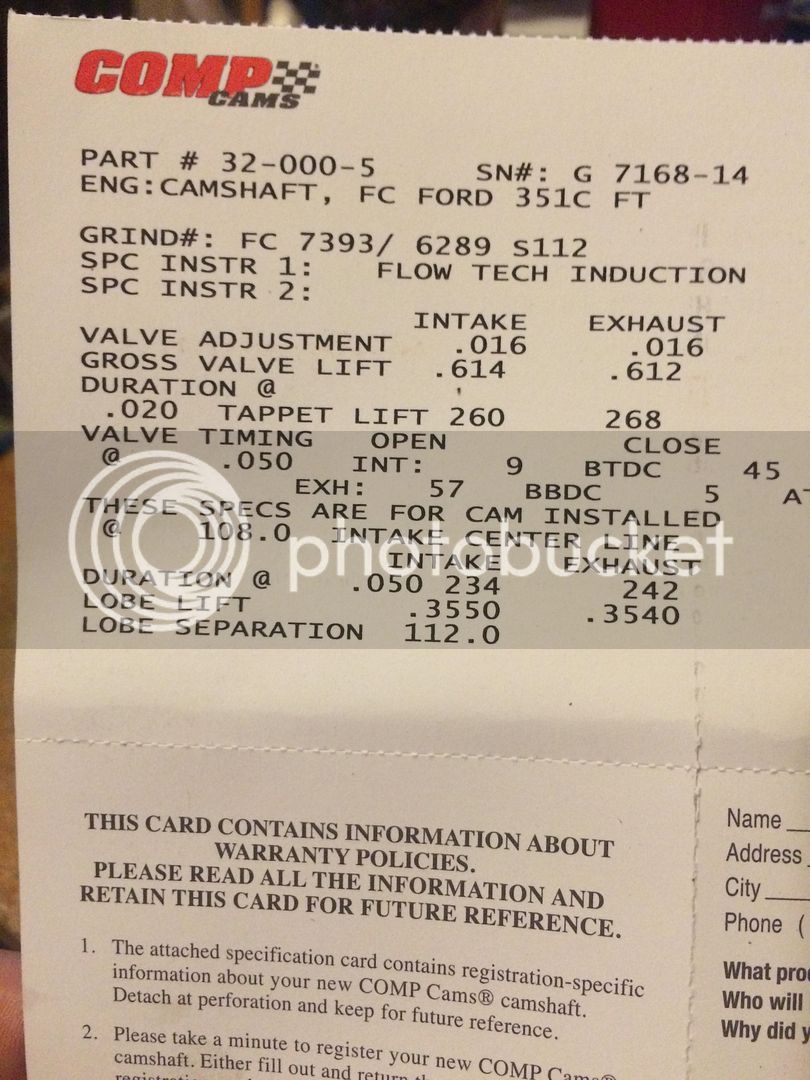
I received my cam and lifters today. Too wrapped up in the holidays to do much until things settle down, but here is a pic of the cam card.

IMG_22191_zps2011d432.jpg


I received my lifter bore hone today so I could finish the bores. The reamer left the bores a little too tight for my liking. This was a 320 grit hone and it took about 30x running it in each bore with WD-40 to get the clearances where the lifter would not have any drag. Tomorrow I'll clean the block one last time and start getting it ready for reassembly. They sure did turn out pretty.

IMG_22391_zps4180e122.jpg


IMG_22371_zps50f7bb17.jpg


IMG_22381_zpsd0f6dcff.jpg


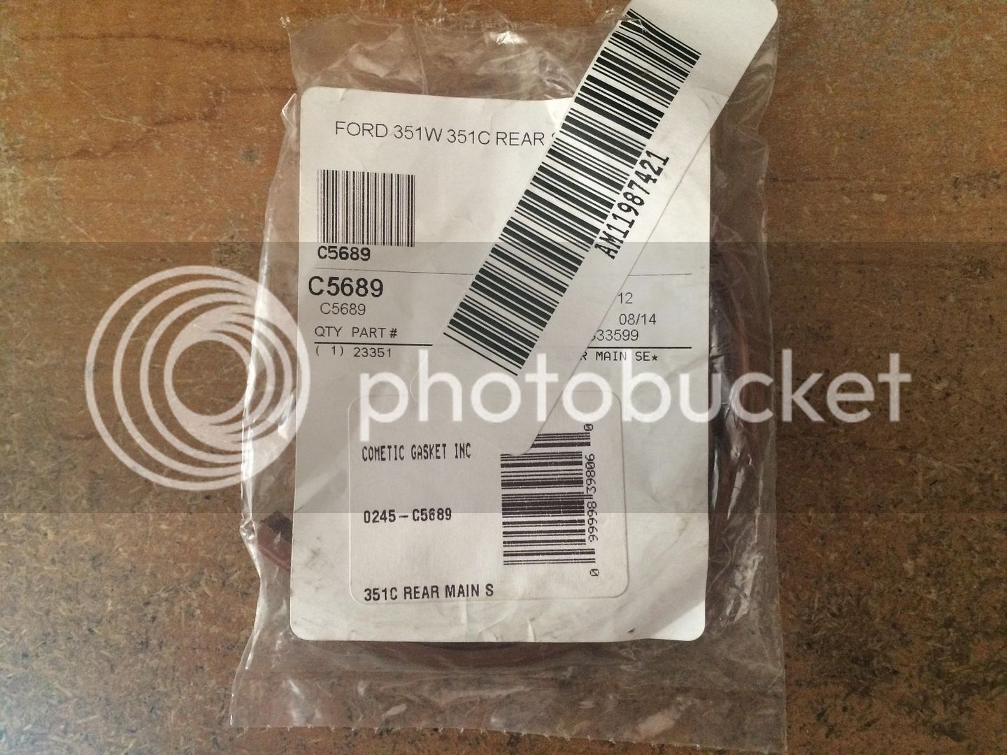
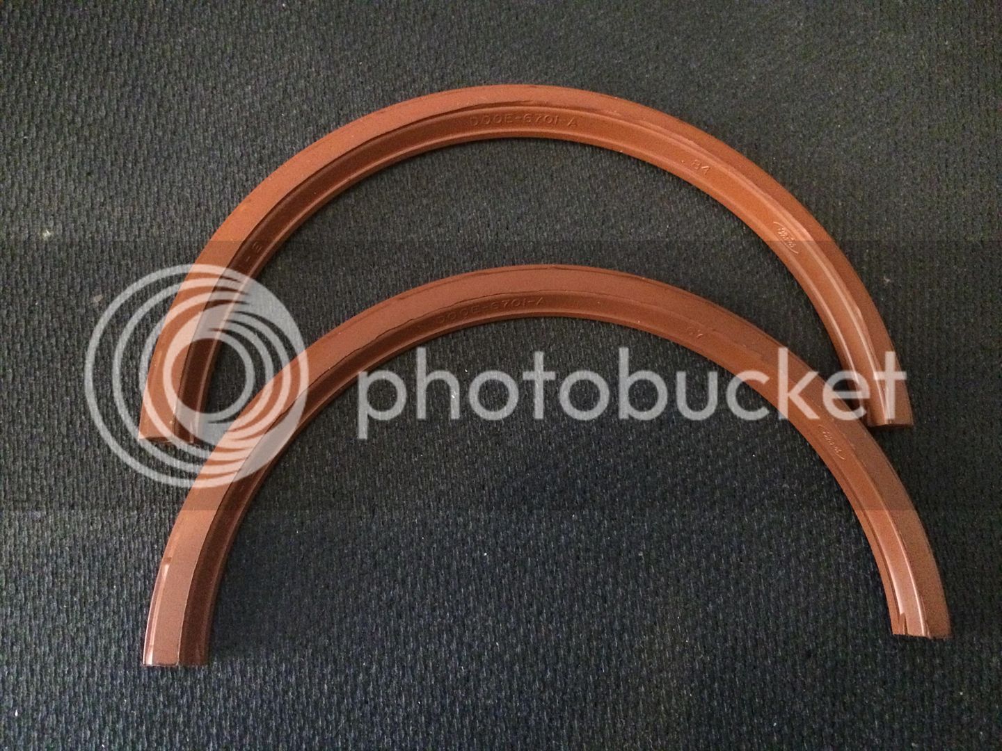
Today I finally received my rear mail seal in the mail so I could start to assemble the shortblock. Turns out getting ahold of the premium quality FelPro rear main seals is about impossible these days. They are all sold out and FelPro has no plans of manufacturing any more. Only the std rubber replacements. I found that Cometic sells a high quality Viton seal and I ordered it for my build. Turns out it has Ford part numbers and such on the seal like it was made under contract. All the better.

IMG_2326_zps9d5de794.jpg


IMG_2328_zps148c961e.jpg


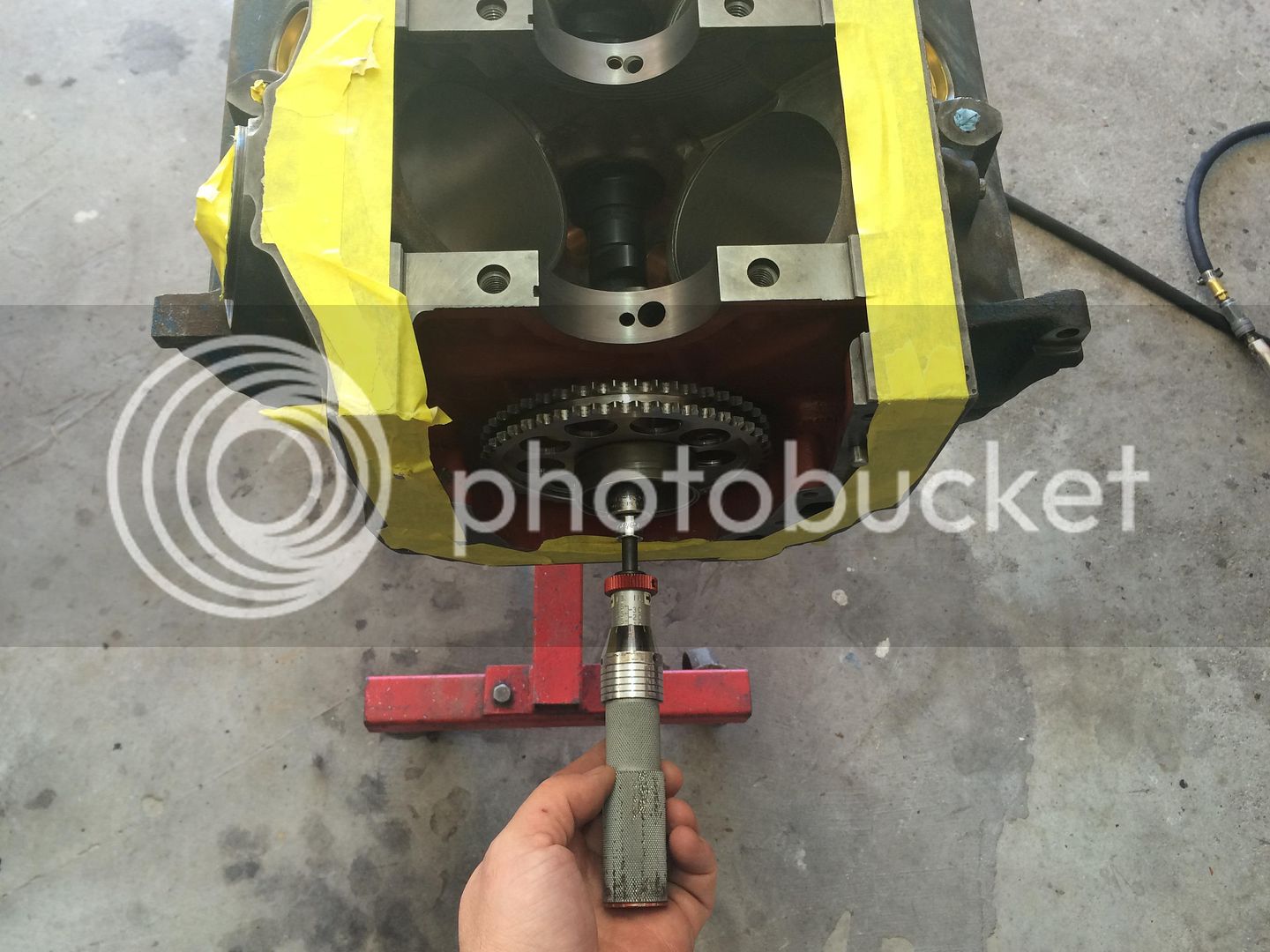
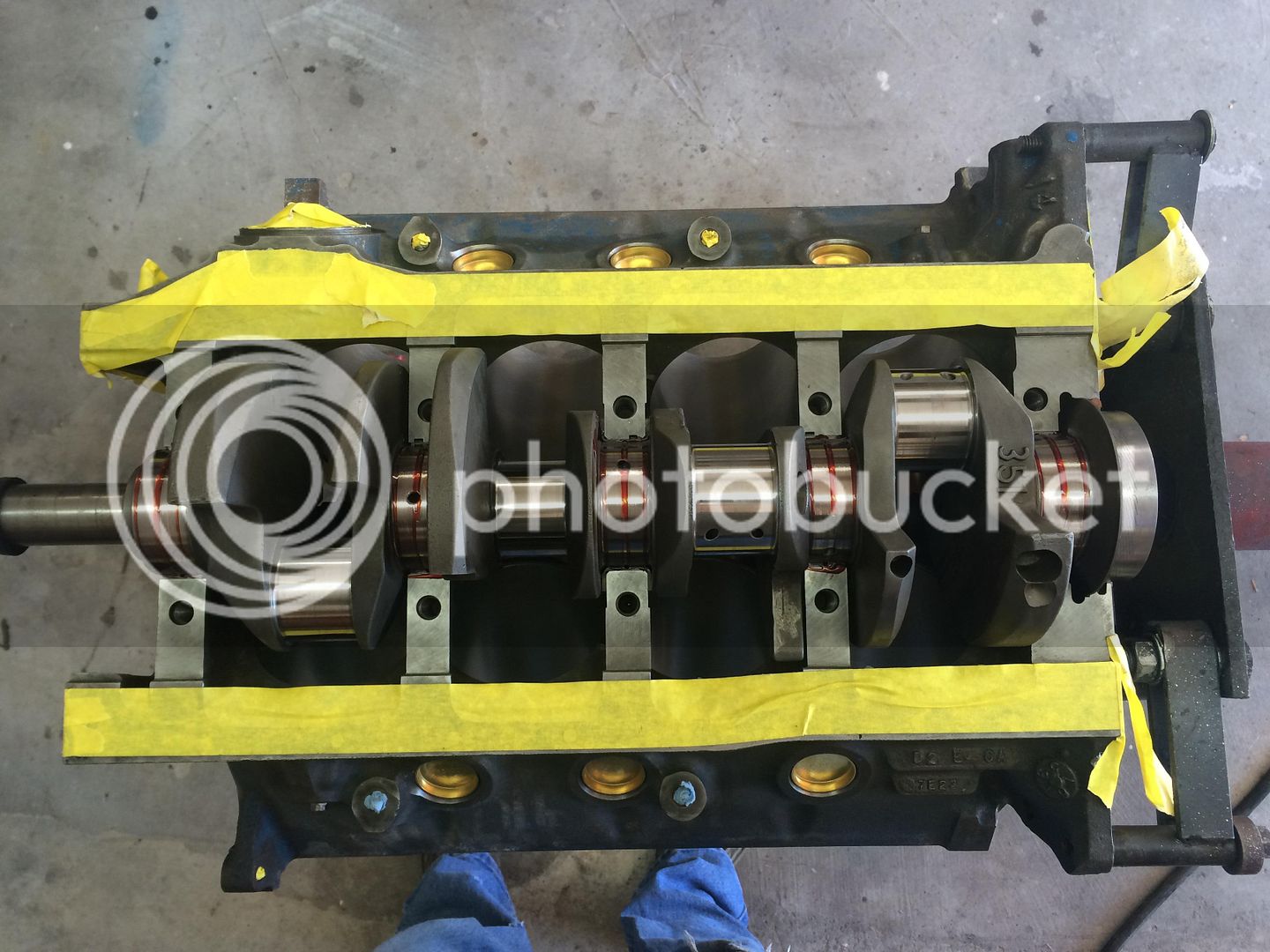
Forgive the yellow tape. I was planning on painting the block but my heads are not back from the machine shop yet. I started to work around the tape but after a bit I just ripped it back off as it was just getting in the way.

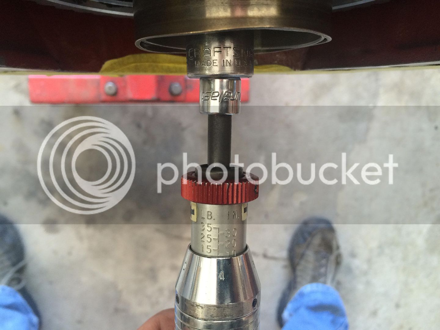
I reinstalled the camshaft bearings after a major block cleaning from all the machine work to install the lifter bushings. Installed all new core plugs. Installed the oil restrictors. Slid in the camshaft and was very pleased that it spun true with no binding or tight spots. It took only 9 in/lbs to turn the cam. It would likely be a bit less without the thick red bearing guard break-in lube.

IMG_2334_zpsf34d7188.jpg


IMG_2335_zps248e744a.jpg


I had a few additional pictures of setting the bearings and crank but Photobucket is being a PITA again so not all of them would load.

IMG_2338_zps3da4add5.jpg


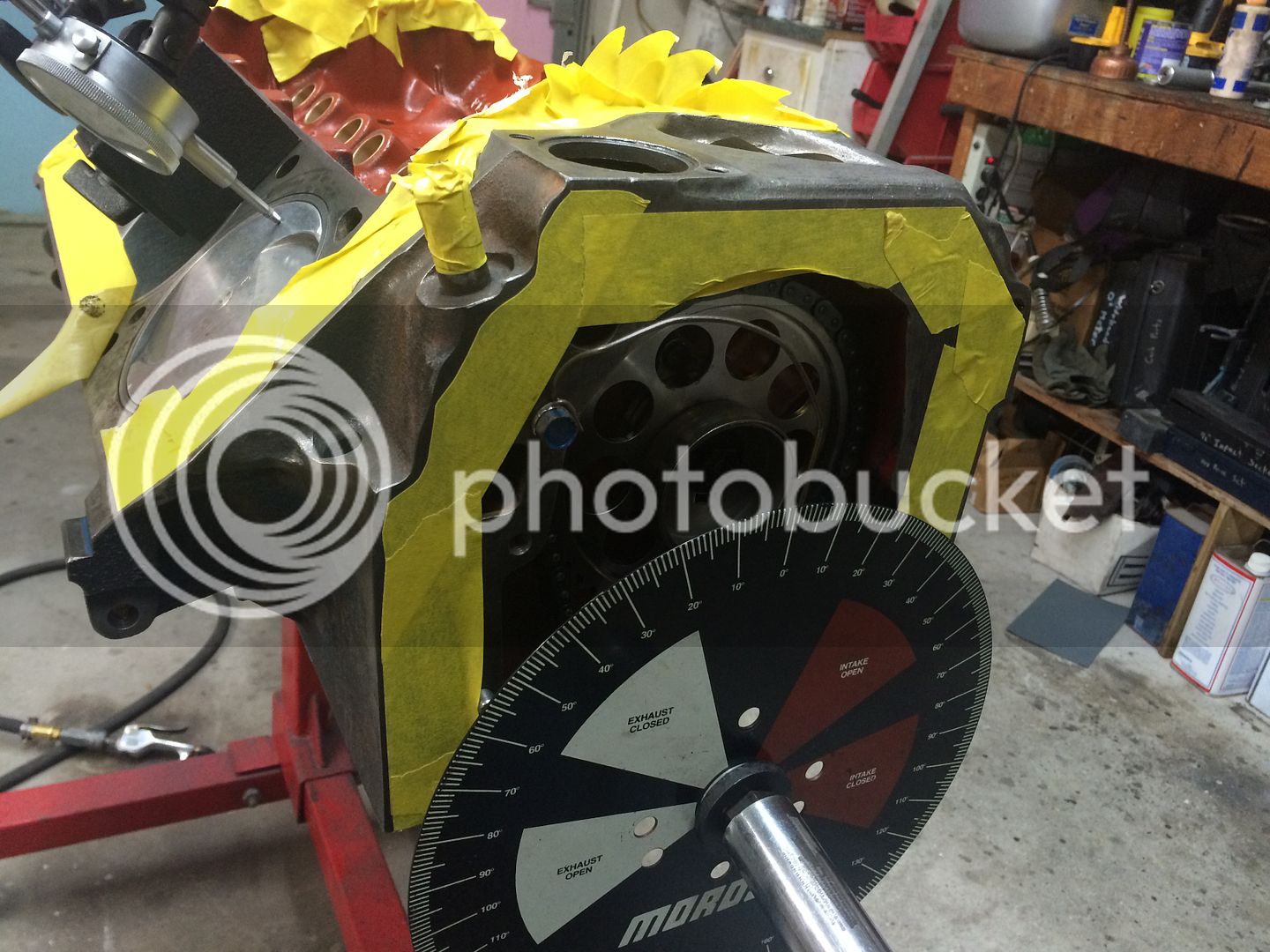
Degreeing the camshaft. Tip... When degreeing a camshaft only install the #1 piston and not all eight. With all the back and forth rotating of the assembly it's much easier working against the friction of one set of piston rings vs all eight. I have a Rollmaster timing chain set with the 9-keyed lower sprocket. The first try had the numbers being 2.5 degrees retarded. After pulling the gears and resetting the lower sprocket to 2deg advanced I tried again but I messed up and was off a tooth on the upper sprocket making the numbers way off. After the third attempt I had all the numbers coming in at +/- 0.5 deg so it was dead on as far as I am concerned.

IMG_2342_zps2670ad38.jpg


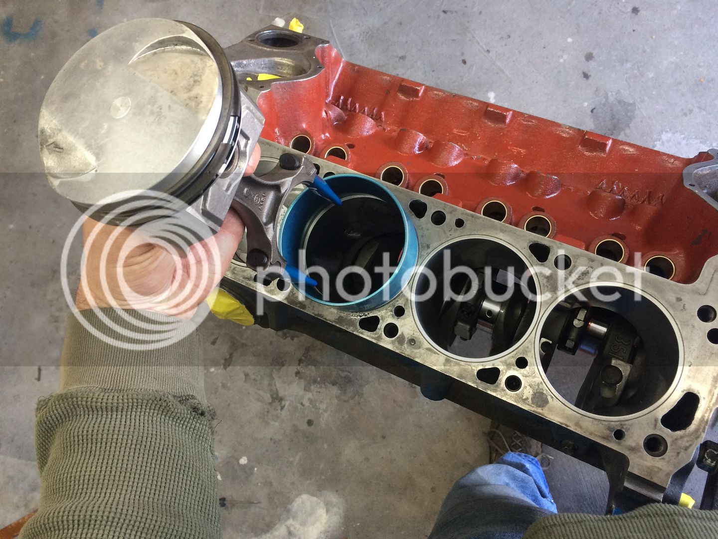
Dropping in the rest of the pistons/rods.

IMG_2346_zps6826eca4.jpg


IMG_2351_zpsbaafa07e.jpg


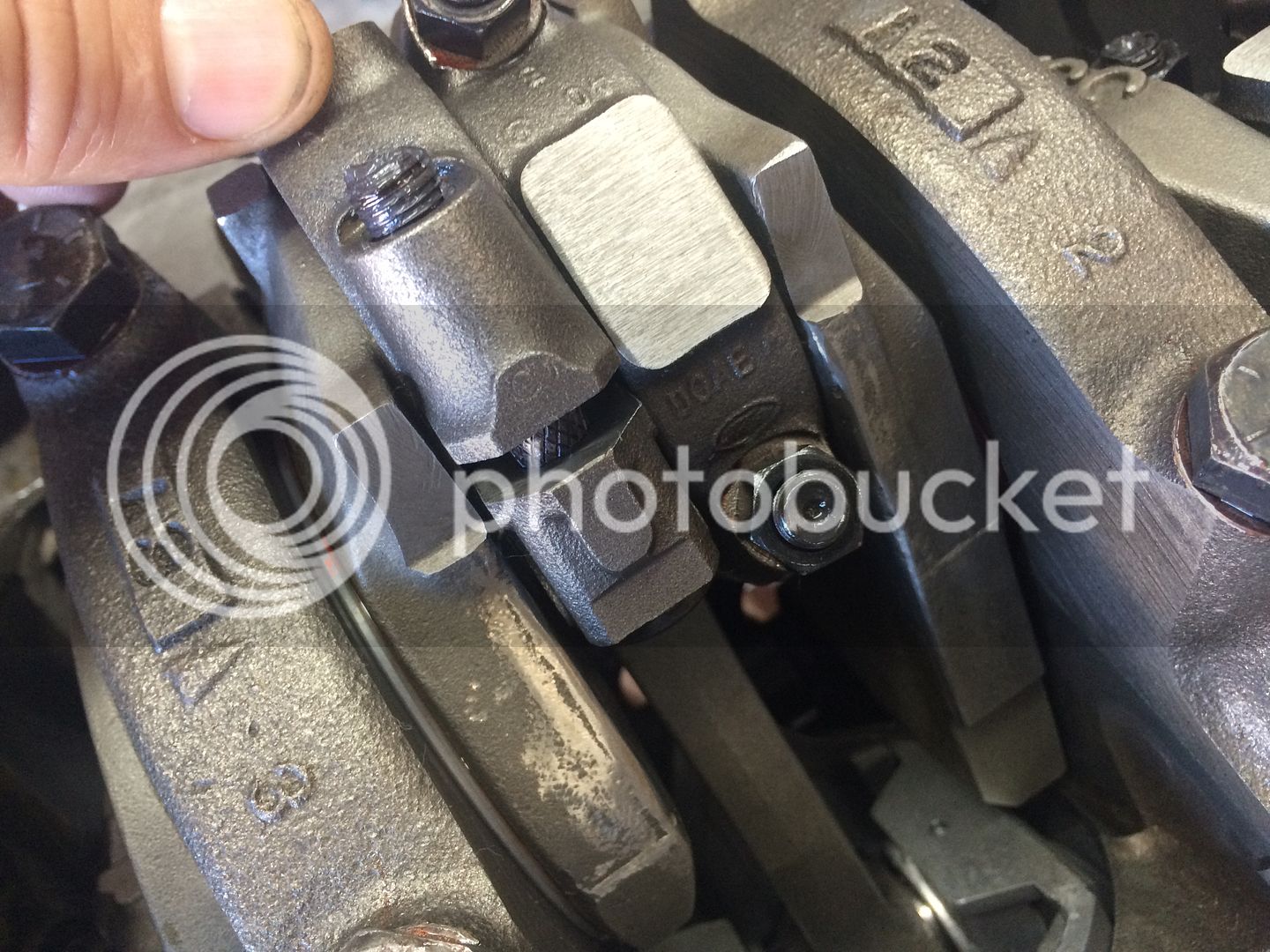
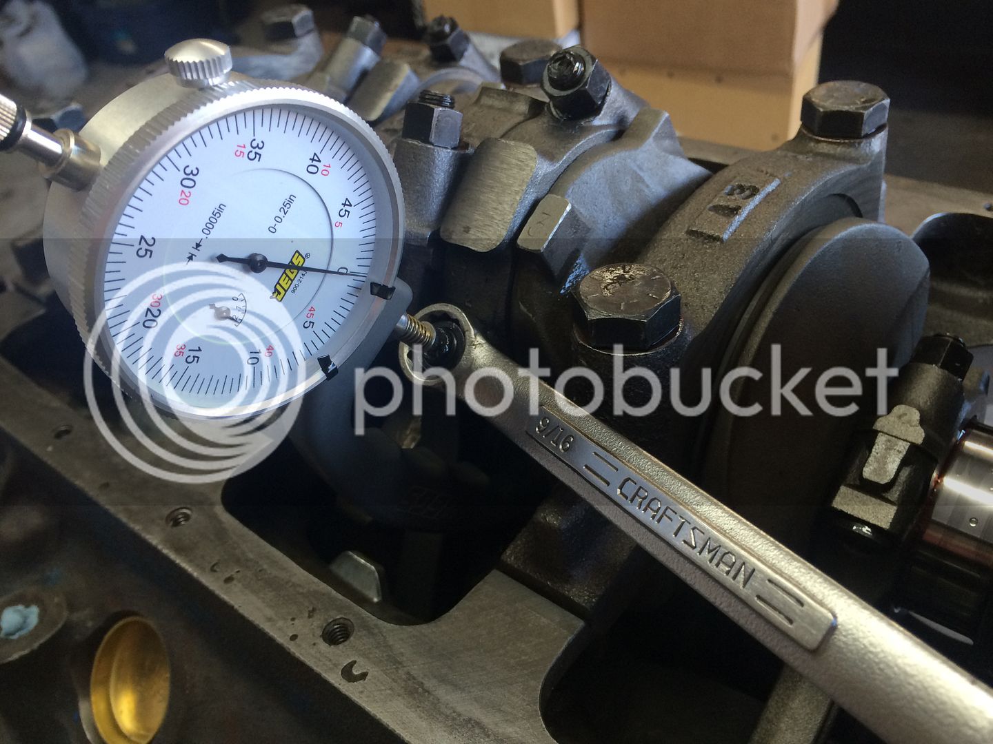
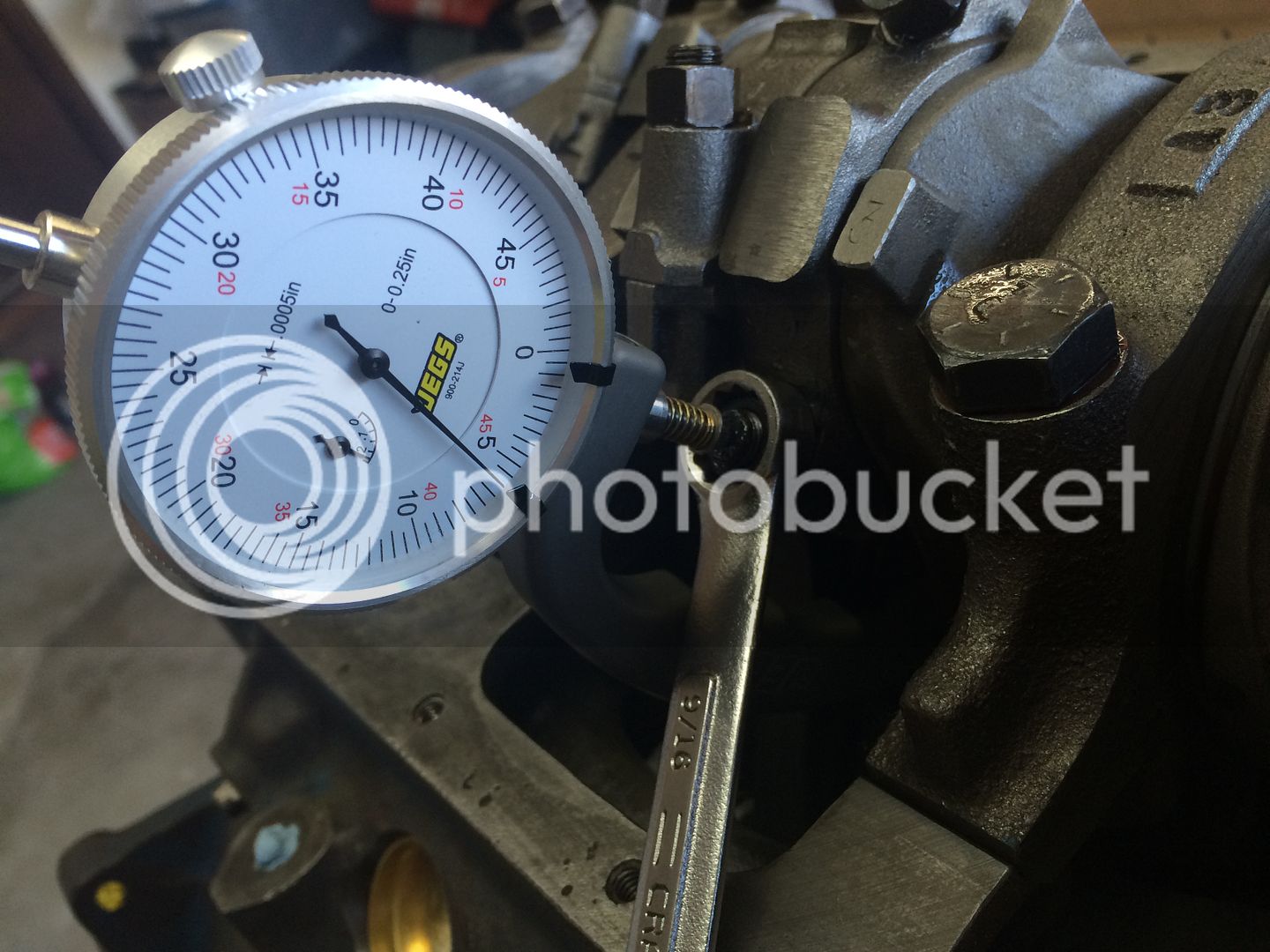
Using my new rod bolt stretch gauge. Specs say .0060"-.0065" of stretch. I gotta tell you, it seems pretty dang tight compared to the usual torque you would put on a fastener. I hope it pays dividends from a engine that I never have a problem with.

IMG_2353_zps70e21712.jpg


IMG_2354_zps7c77f3a1.jpg


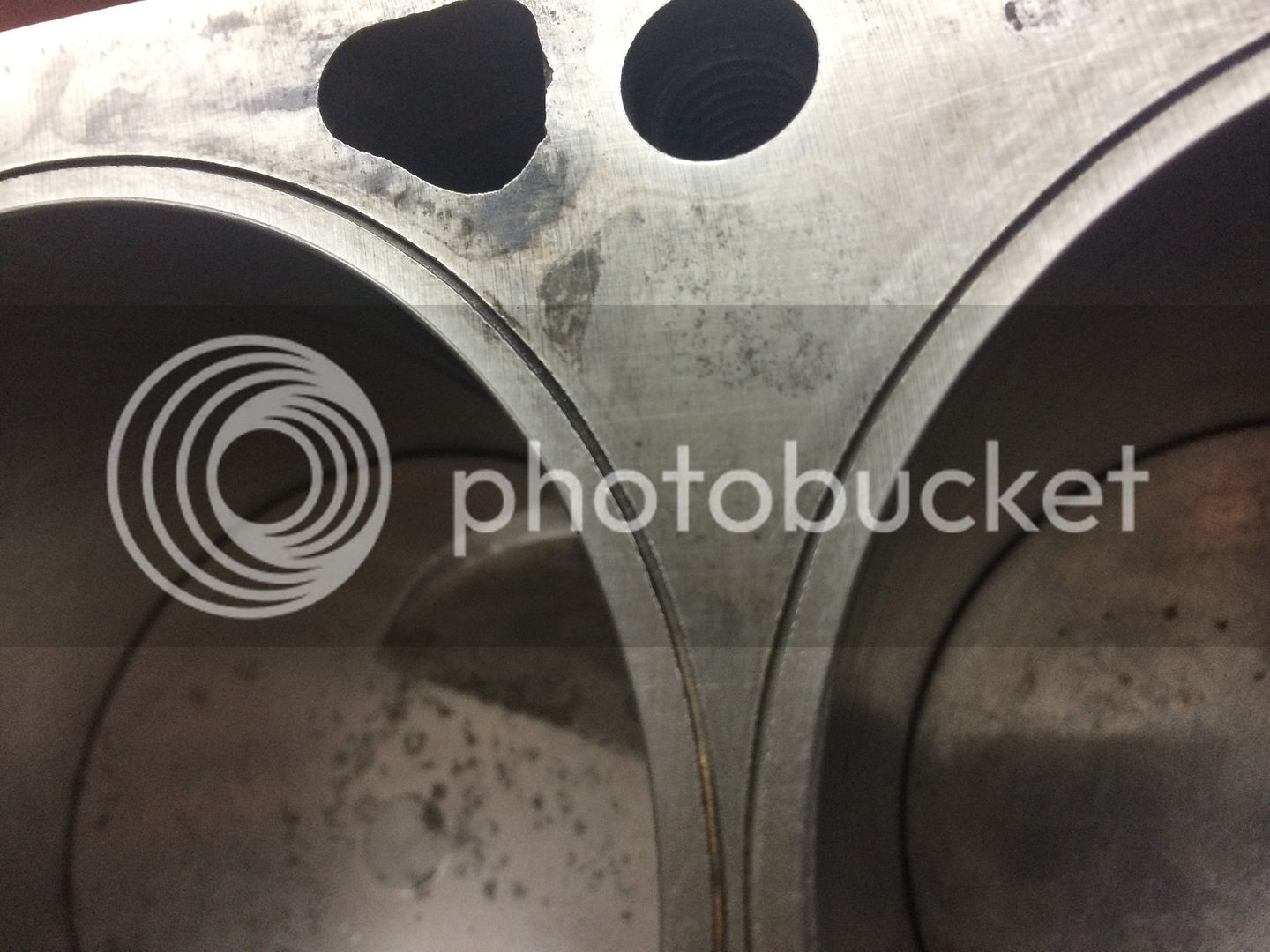
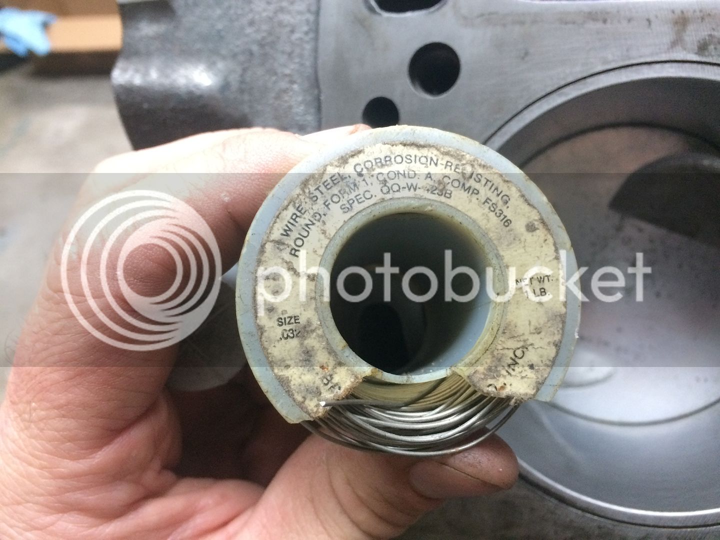
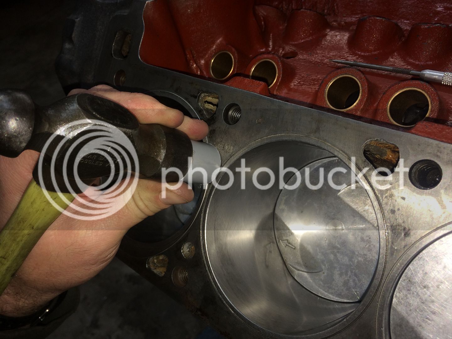
I also needed to replace the o-rings that the block was last machined for when it was built by a race shop in Australia. The story was it was for a drag boat. Whatever the case, it showed good machine work throughout. I purchased a o-ring kit from Summit racing. apparently .041" wire is the standard as it is the only wire diameter offered. I bought the kit about two months ago. Now hat it came time to use it it would not fit into the grooves. After some quick measuring I discovered the block was machined with a .030" groove and not the US standard of a .040" groove. As luck would have it, I had a roll of .032" stainless steel "safety wire" that fit the bill perfectly. I used the plastic installation tool that came with the kit and it all went in quite easily. This is not something that I would have ever had machined into a block, but since this is what I had to work with, it needed to be redone. Once I got rolling it took less than 20 minutes to install all eight rings.

IMG_2355_zpse039e85d.jpg


IMG_2357_zpsa9d20d8e.jpg


IMG_2359_zps22d98cd1.jpg


Next is hoping that I get the heads back soon. Then I will need head gaskets and measure for the 3/8" pushrods. Oil pump, oil pan, timing cover etc, etc..

 
You may want to chamfer the ends of the pushrod holes in the head to prevent any clearance problems. Another lesson I learned the hard way. Looks like a great build. Chuck

 
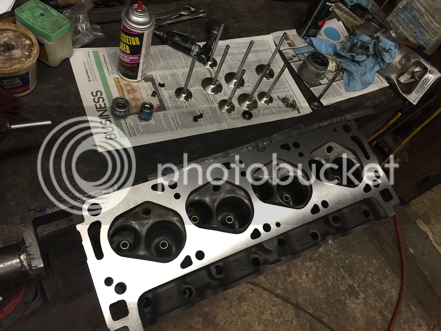
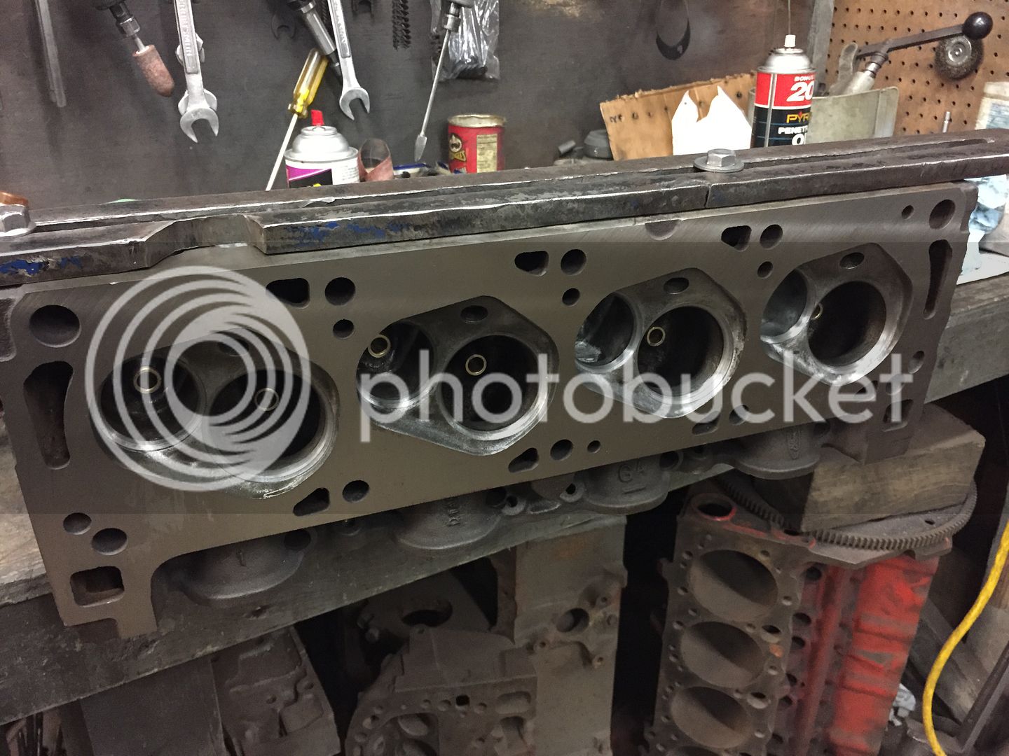
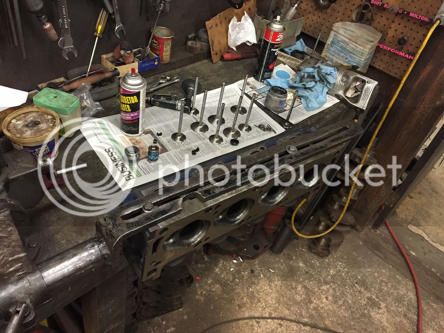
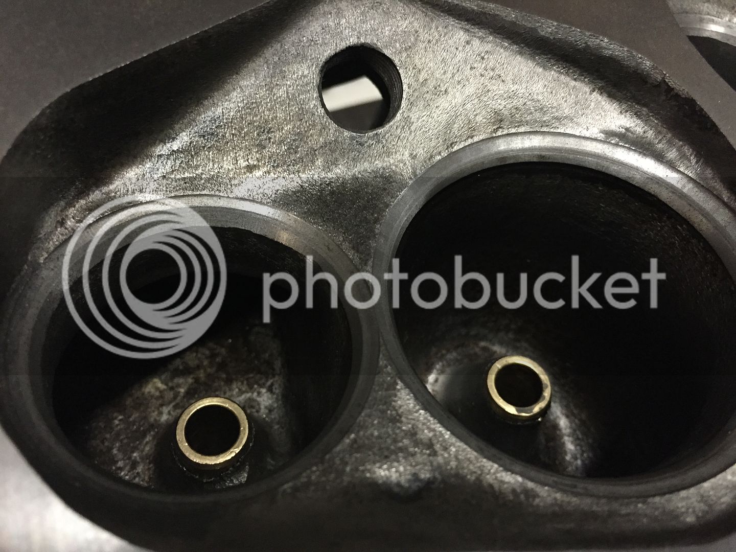
Some progress. Not much. Heads were skimmed solid bronze guides installed, machined for studs and guide plates, multi angle valve job. Heads would have been done but the machinist ran into a snag with the exhaust valve height. Intake valves were perfect at 1.800". They were all coming in at 1.700 on the installed height for the valve springs. We ran around options of different keepers, retainers, spring seats as more machine work would compromise the head and seat integrity. I called up Ferrea and they agreed to exchange the valves for ones that are .100" longer which would be perfect. I just need to pay for the shipping. Definitely the best solution.

IMG_2520_zpsw1ae9ben.jpg


IMG_2518_zpsuskqemgw.jpg


IMG_2519_zpstgvekcze.jpg


IMG_2521_zpsrvek6ztg.jpg


Just a tip, shamfer around the combustion chambers to take off the sharp edges off from the machining process to help eliminate hot spotting. An easy, but overlooked process that should be done to all cylinder heads after resurfacing. Looking good and all the best with the build.

 
What size holes have you decided on to drill into the bushings? Chuck
The instructions recommend a .043" hole. I'm going with a SFT cam so that should be fine. If it were hydraulic or a roller cam it might be necessary to drill a larger hole. I'd think a hole the same size as the one in the side of the lifter would be appropriate. Most are .125" or 1/8". That would allow maximum pump-up flow on cold starts.
There is a definitive mathematical science to this hole size and any larger than .040, the hole will no longer be a restrictor. If you know the math, .040 is what you want.
What is the the math that lead you to this conclusion? Chuck

 
There is a definitive mathematical science to this hole size and any larger than .040, the hole will no longer be a restrictor. If you know the math, .040 is what you want.
Definitive math. No such thing in this business.

So many people second guessing every step of this build. Quite disappointing.

 
Back
Top