Here you go... Quick and dirty
My test is wired like this
Battery 12 v - - - - tach------ Batt terminal on Hei distributor
Tach output on hei distributor is not used in this case.
I know car runs like crap but that is going to be another thread...
Cheers
Alex
Sent from my ONE A2005 using Tapatalk
Alex,
Nice! One question. The wire from battery,crimped together to the tach is connected to the exposed terminal? So the tach is reading from the one wire?
Mustang7173
Hi,
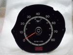
These original tachometers are operating based on the current fluctuation .
So +12 volts is connected to one terminal on the tach, then from another tach terminal it is connected to the batt post on HEI distributor.
So , when its idling, the tach is recording frequency going trough it and moves the needle accordingly...Step on the throttle, and Hei turns faster and frequency changes and the needle goes up....
That's all there is to it.
This logic only applies to the old 2 wire tachometers. New tachometers read specific signal sent by tach terminal on HEI which is then decoded in the tachometer ... they usually have 3 or more terminals...
Pink wire connected to original tach in your mustang is resistance wire... It drops 12 volt to 7 volts. It would cause lots of issues if you were to attach it to the batt terminal on HEI
HEI Needs switched 12 volts. So replace pink resistance wire with solid copper wire and plug it to the batt terminal on hei and your tach should work just fine.
Here is the sample diagram. + on ignition coil corresponds to BATT terminal on HEI
Alex


")