- Joined
- Jun 14, 2019
- Messages
- 571
- Reaction score
- 174
- Location
- Coachella Valley (Palm Springs)
- My Car
- 1973 Convertible, 351 4v CJ, C6, Mach 1 Decor options, power: steering, brakes and windows, a/c, Rally Pac gauges, Deluxe interior.
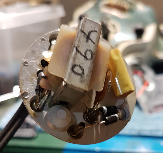
[url=https://ibb.co/ZVjjKXW][img]https://i.ibb.co/zrMMbxG/s-l1600-2.jpg[/img][/url]
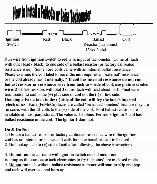
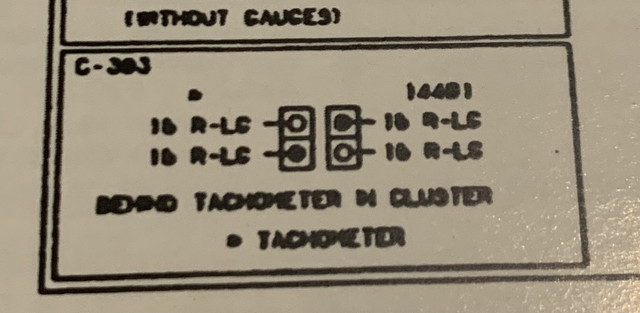
The only info on the tach is at the bottom on the left of the column of boxes on the right. I took a close-up c-383 and it doesn’t say anything about the resistor, although it’s plainly shown in the diagram.Thanks for the wiring. I got almost the same, only, my doesnt have the small pics that is around yours. 1 question anyhow, I cant read the letters on the small pics. Does it say somewhere any values/numbers for resistors or the tach on the small pics under the wiring diagram?
The repro of this diagram is not the greatest.
 ....
....