429 internals: Need some help...

7173Mustangs.com

Help Support 7173Mustangs.com:

This site may earn a commission from merchant affiliate links, including eBay, Amazon, and others.
Joined
Mar 30, 2017
Messages
2,338
Reaction score
822
Location
The Netherlands
My Car
73 Grande 351C
71 Mach 1 429CJ
Finally got my gasket set, so was back on the 429...

I'm totally not familiar with this engine (and did not open it either). While busy came across some weird stuffs...

So got 5 questions, hoping someone can help me...
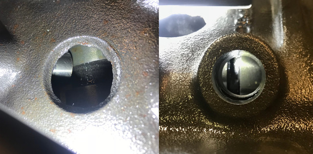
hole_q1.jpg


#1

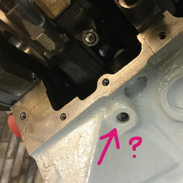
there is a hole with athread on the block, (was busy placing the oil pump back, so engine is upside down)

its on the rear on driver side. If i blow, the air goes out somewhere. without restrictions. Is it part of the cast and do I need a plug or something?

excentric_q2.jpg


#2

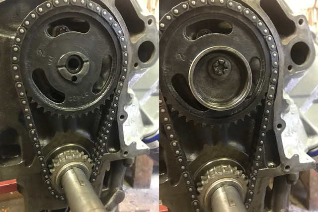
On the doc I have there is nothing to be seen on this, except i need align the dot of the bigger gear to the 0 mark on the lower gear

of the timing chain. So far so good, but then, got that excentric thingy for the fuel pump, that is if i follow the drawings, bolted on with the cam bolt.

but there is nothing that prevents it to rotate if by some reason the bolt would come loose. Is this normal or the propper way to add that thing?

As I will place an EFI later on, I don't need it but thought, may something hapend, I may like be able to put a carb without opening the engine again.

So question is, is it really the way it should be placed?

gasketquality_q3.jpg


#3

The engine came with buckets of parts, nuts, bolts and gaskets. As I was missing the intake, the oil pan and exhaust ordered a full set.

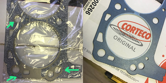
So got this Felpro set, also with head gaskets. I've open the other pack i was already having and compared them.

The brand is Corteco, and they have reinforcement in metal that the flepro are not having (felpro has just a ring in metal around cyl shapes)

Which one shoudl I use? they seams be as thick. Wondering if the Corteco, with the extra metal would go "flat" as the flepros..
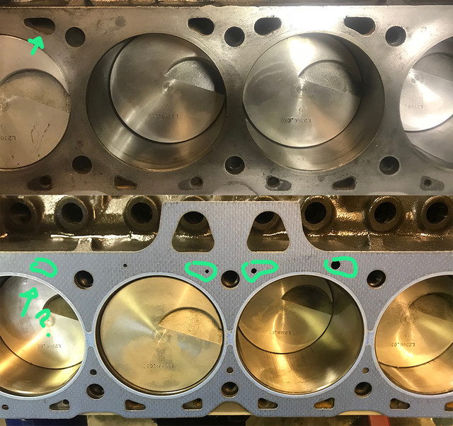
headgasketholes_q4.jpg


#4

I recall from a long time ago, that i was told, I should pay attention I get the propper gaskets for a CJ. So while inspecting, i saw water passages are

either closed or very restricted. Both sets have same holes. On the heads the water passage do match. So question is, is it normal, or should I open them?

Its weird to have water passages from block to heads and have these closed by a gasket...

lifters_q5.jpg


#5

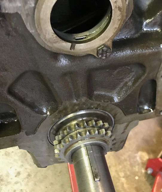
This one worries me most. Installed the new cam with tons of assembly lub from Lucas. So far so good, but when I've placed back the chain

I saw the cam needed go deeper. No big deal, except, I see the lobes ar enot matching the lifters guides.

Added one lifter and its clear they are not aligned.

chain_q5_2.jpg


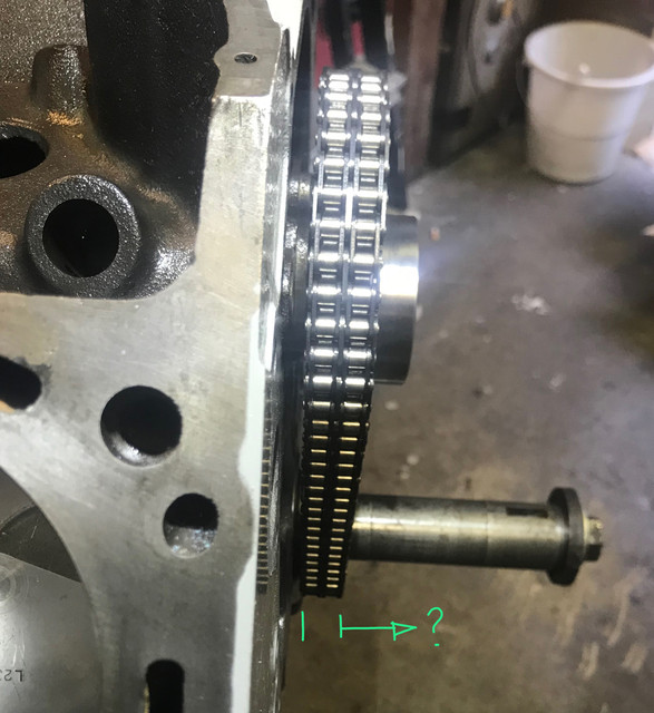
On this pict, the chain is aligned with the lower gear, so as the cam can float, I wonder if I need to move the lower gear toward the front of the engine?

The lower gear was still on the crankshaft. Or is there some kind of spacer I need somewhere?

Also if I need to move the lower gear how do I do this? There is a, say 2 inches, long piece of metal on the crankshaft, I tried to tap it out, but I would not move. Do i need tap it with greater force and then only the gear would then came out, or do i need extract the gear a bit and it would be guided by this little metal part? From what I can see on lobes, it looks like i would need to have the cam bit forward by say a 1/4 of an inch, 5 or 6mm.

I could provide more picts if required... behind the top gear, there is only a plate with 2 bolts that holds the cam, and I have tried rotate the engine while pulling a bit and the cam would then be aligned, of course, the lower gear is then no longer aligned... so it would need go forward the engine. I wonder then, if there should be some kind of spacer behind...

If someone have clues, some light would be very welcome...

 
Just found these regarding my q #5.

This is normal they say... ment to create some rotational movement on the lifter, equal wear as the cam goes forward the engine while operating on 385 series...

I've also seen some lifters are more off than others.

Man this is a scary engine, gimme a cleveland!

https://www.460ford.com/forum/37-engine-tech/158631-429-460-cam-lifter-alignment-issues.html

https://www.ford-trucks.com/forums/677106-cam-lob-alignment.html

For #2, a cleveland has a small bits of metal(pin) that goes into the timing chain, and once tightened, it won't move.

like this one

https://www.ebay.com/itm/NOS-OEM-Ford-D5AZ-6287-B-camshaft-eccentric-1973-74-75-76-1979-302-351W-engine/362236400356?_trkparms=aid%3D222007%26algo%3DSIM.MBE%26ao%3D2%26asc%3D52885%26meid%3Dc1cf51fbd7b340fdb5db9be347fadfd4%26pid%3D100005%26rk%3D2%26rkt%3D2%26sd%3D321292300301%26itm%3D362236400356&_trksid=p2047675.c100005.m1851

The ORIGINAL 429 has a smooth surface no pin (the one on my picts).

found this:

"The ORIGINAL solid 1 piece fuel pump eccentric did not have a dowel pin hole; (it was glued to the calm gear with a contact cement. Heat and time usually broke down the glue)."

so it is wise to let it on knowing i will use an EFI? and should I add a washer of equal thickness if I remove it? Or would it be wise to get a newer version and install it anyway in case the weight is somehow taken in account in cam assembly and would somehow create vibrations if I remove it completly?

 
Last edited by a moderator:
#1 - block drain - 1/8" or 1/4" NPT usually

#2 - Usually there is a tang that goes into the hole in the face of the cam gear.

#3 - Either one should be fine. I personally would use whichever one is thinner

#4 - Normal - holes are steam holes to allow air and gasses to purge into the head and out through the t-stat housing. If there is an "UP" or "FRONT" stamp on the gasket, pay attention to that when installing the heads.

#5 - Lifters don't sit square on the lobes, and the lobes are tapered to induce rotation.

As far as the timing set, what is the manufacturer and model #? There are different sets depending upon the year and IIRC, one may not work with the other.

 
#1 - block drain - 1/8" or 1/4" NPT usually

#2 - Usually there is a tang that goes into the hole in the face of the cam gear.

#3 - Either one should be fine. I personally would use whichever one is thinner

#4 - Normal - holes are steam holes to allow air and gasses to purge into the head and out through the t-stat housing. If there is an "UP" or "FRONT" stamp on the gasket, pay attention to that when installing the heads.

#5 - Lifters don't sit square on the lobes, and the lobes are tapered to induce rotation.  I think you need to flip the crank gear around.
thx for the reply, 

#1 ok, will try to find something to close these

#2 yes, thats what i see on newer 385, but original one (and in my own reply) is perfectly flat and smooth, found n some forum, it was glued... how weird.

question is now, should I keep it, as i want EFI and will not need this. or should I install one, for some balance reasons (if cams assembly take this in account)

#3 ok, well they have same thickness. will look on which side the coin lands to make my choice :)

#4 ah, just for the bubbles ok... Yes I check everything at least twice :)

#5 What do you mean? invert the gear orientation? It was already on this way (and markings to align are also visible). 

From the side, I don't think the shape would be work if rotated. I would try, if I could get that thing out in the first place. Do I need tap that retainer piece of metal like crazy to get it out? Is there a good trick to get it out?

 
Last edited by a moderator:
#1 - block drain - 1/8" or 1/4" NPT usually

#2 - Usually there is a tang that goes into the hole in the face of the cam gear.

#3 - Either one should be fine. I personally would use whichever one is thinner

#4 - Normal - holes are steam holes to allow air and gasses to purge into the head and out through the t-stat housing. If there is an "UP" or "FRONT" stamp on the gasket, pay attention to that when installing the heads.

#5 - Lifters don't sit square on the lobes, and the lobes are tapered to induce rotation.  I think you need to flip the crank gear around.
thx for the reply, 

#1 ok, will try to find something to close these

#2 yes, thats what i see on newer 385, but original one (and in my own reply) is perfectly flat and smooth, found n some forum, it was glued... how weird.

question is now, should I keep it, as i want EFI and will not need this. or should I install one, for some balance reasons (if cams assembly take this in account)

#3 ok, well they have same thickness. will look on which side the coin lands to make my choice :)

#4 ah, just for the bubbles ok...  Yes I check everything at least twice :)

#5 What do you mean? invert the gear orientation? It was already on this way (and markings to align are also visible). 

From the side, I don't think the shape would be work if rotated. I would try, if I could get that thing out in the first place. Do I need tap that retainer piece of metal like crazy to get it out? Is there a good trick to get it out?
#2, because it can be placed in any orientation, it is not balanced by the cam. Whether or not you keep it is up to you. I would use blue thread locker on the back side of it to "glue" it to the cam sprocket if you do keep it.

#5, if the timing/orientation marking is visible you likely have it on correctly. Edit: see below.

Did you check the freeplay on the camshaft? If it is good and the thrust plate is down all the way it should be OK. One thing to check, is if the cam bearing plug in the back of the block was installed too far in, that would keep the cam from going back as far as it should.

If you decide to leave the fuel pump eccentric off you'll need to replace it with a hardened washer, at least a grade 8.

Edit: I looked at the pictures closer, and I think that Hemi might be right, I believe the crank sprocket is on backwards. That sprocket may have timing marks on both sides. I believe the raised portion next to the crankshaft should be facing inward, and the face of the sprocket that faces out should be smooth.

 
Last edited by a moderator:
because it can be placed in any orientation, it is not balanced by the cam. Whether or not you keep it is up to you. I would use blue thread locker on the back side of it to "glue" it to the cam sprocket if you do keep it.

#5, if the timing/orientation marking is visible you likely have it on correctly. Edit: see below.

Did you check the freeplay on the camshaft? If it is good and the thrust plate is down all the way it should be OK. One thing to check, is if the cam bearing plug in the back of the block was installed too far in, that would keep the cam from going back as far as it should.

If you decide to leave the fuel pump eccentric off you'll need to replace it with a hardened washer, at least a grade 8.

Edit: I looked at the pictures closer, and I think that Hemi might be right, I believe the crank sprocket is on backwards. That sprocket may have timing marks on both sides. I believe the raised portion next to the crankshaft should be facing inward, and the face of the sprocket that faces out should be smooth.
#2

Ok, so you say, if I put it back use some blue thread locker (any picts/brand so I can find the equivalent here?)

if not, I need a washer. ok, crystal. But why such a strong one? What kind of stress is apply to it? The eccentric piece on itself is receiving only the side pressure of the fuel pump (if any) as a pump will not be reused, in my old brain, I thought a washer with the thickness of the old eccentric metal would then be there just to mimic the same potential traveling distance if the cam moves forwards at times. Being sandwiched with the cam bolt. Just wondering why it needs be that strong?

#5

I don't mind try to look now, I even tried but can't remove that metal lock thingy in front of it. How do you get it out? I tried tap with flat screwdriver and small hammer and it went a bit higher, but did not move after that and didn't want to damage it. Any tips on how to remove it if I need to remove it at all? (may be the gear can use it as a sort of rail, I dunno).

For the gear on itself, I will need some puller that is long enough, the ones i have were too short for this engine. So if 1/2 way or less, I don't see if any marking then its correctly oriented. Correct?

Wish I would have open this engine myself...

 
#2 because it has to hold the cam sprocket on. A regular soft washer can get what is called plastic deformation, which would allow the bolt to lose torque, come out with catastrophic results. The bolt that holds it on is at least a grade 8 bolt, the washer has to be the same strength.

#5, that is the key, which is in the keyway, and it runs under the sprocket and is what keeps the sprocket in the correct orientation on the crankshaft and keeps it from turning on the crankshaft. You cannot remove it with the crank sprocket on. The sprocket has to be removed with a gear puller.

 
Crank sprocket should slide right over that woodruff key. Tap it back down into the crank. The key is what drives the cam.

****edit ----- Dammit - Don beat me to it

 
found an older pict with the gear alone...
Interesting, maybe it's an optical illusion or camera parallax that makes the crank sprocket appear to be too far in.

I would suggest taking the chain off and use a straight edge across the teeth face to make sure whether or not they align.

 
found an older pict with the gear alone...
Interesting, maybe it's an optical illusion or camera parallax that makes the crank sprocket appear to be too far in.

I would suggest taking the chain off and use a straight edge across the teeth face to make sure whether or not they align.
I did that as i was trying to figure out how this offset was possible, measure with and w/o the chain, its perfectly perpendicular to the crankshaft. If I turn the engine while i pull the camshaft toward me (toward front), I have some play, then the alignment issue is practically gone. I didn't pull hard as the game is to not damage the chain... was trying figure out how to regain some matching area of the lifter on the lobes. Thats also why I was wondering if there were any spacer missing, that would be placed behind the gear (crank sprocket ). Ideally, if there was say 5mm displacement of the current position toward the front, the lifters would then be say 60+ % on the lobes vs the 30% that they are now. If the cam would then move forward by few mm, it would likely be 100% or near of it.

I also meanwhile search at chains picts, and found some with double roller chains, also have the "boss" or whatever the extrusion in front is called. Most single and many doubles are indeed having a flat surface in front. So I guess, I need pull that baby out at least an inch to see what's behind...

So you say, it will glide over that "key" like if on a rail... I should be able to build some plate to hook it to one of my pullers (it's sunday and all is closed). It should not need much pressure I think..

its late here (or very early), will try later today. Thanks both for the help!

 
Last edited by a moderator:
In operation the camshaft moves to the front, due to the oil pump being turned by the distributor gear.

The end play (freeplay) of the camshaft, front and back should be 0.001 to 0.006 inch (0.025 to 0.152mm), so you won't be able to get a few millimeters.

 
Last edited by a moderator:
Got it out, it was correct, the back side has a machining to fit the crank shape. I’ll post images later on but if i measure and check alignments, it all add on. At this point I think the diff was caused by the upper gear not engaged enough onto the cam. I did not torque the cam bolt when I saw the alignment diff. If I check how far the cam can come to the thrust plate and how deep the top gear should go on the cam, then lobes align much better. Reinstalling now...

 
Fabrice, how much end play do you have on the cam? As Don noted, it should be very little. I did a little digging and from the factory , the 429CJ had a spacer that went behind the cam gear. If you are missing that spacer, and the timing set was designed to use it, that's your problem.


K, all back in, this time bolted the cam to the point I’d need to torque to specs,(which I can’t find) and now all aligns, even have the dist in to check the gear, all turns smooth and aligns.Guess that was the prob. As I’ve now all removed, super clean and all in assembly lube, I think the top gear to cam might have been the prob where it wasn’t perfectly engaged and did not go deep enough on the cam.

All looks and feels good now, so now its all about finding that cam bolt torque... brw do I need some lock paste? Manual doesn’t say...

 
The torque specs for the camshaft sprocket and thrust plate are on page 21-24-31 of my '71 shop manual. The torque specs for the camshaft sprocket to camshaft bolt is 40-45 foot-pounds, the thrust plate is 9-12 foot-pounds.

 
Back
Top