I need help diagnosing what's wrong with my engine

7173Mustangs.com

Help Support 7173Mustangs.com:

This site may earn a commission from merchant affiliate links, including eBay, Amazon, and others.
No, the resistor wire connects to the coil, only. The wire that connects to the "S" terminal on the solenoid should receive around 12 volts when cranking the engine.

Yes, the HEI distributors require 12 volts, so if it were wired correctly someone figured out how to power it with 12 volts.
I'm really sorry that I'm so confused about this.  Here's what I have going on:

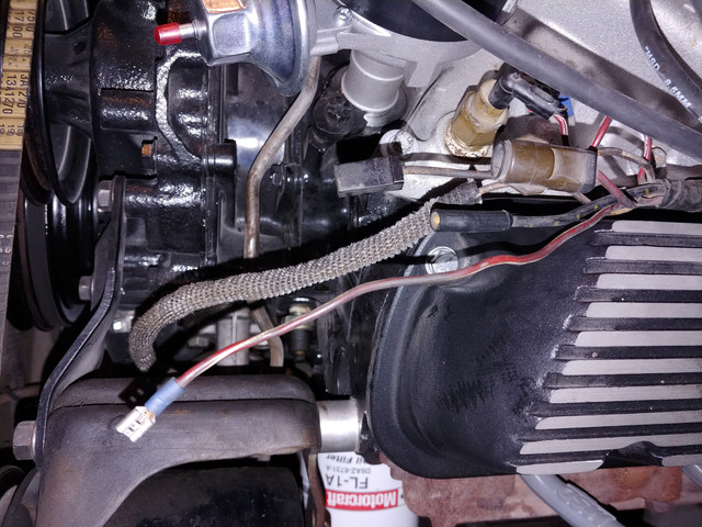
The 4 wires on the driver's side of the manifold are all unhooked.  I believe two of those were hooked to the HEI, but of course I'm an idiot and didn't take a photo.  I imagine one of those is the output of the pink wire?

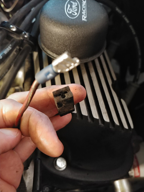
I'm guessing these are the 2 that were hooked up, given that the are the only female spade connectors


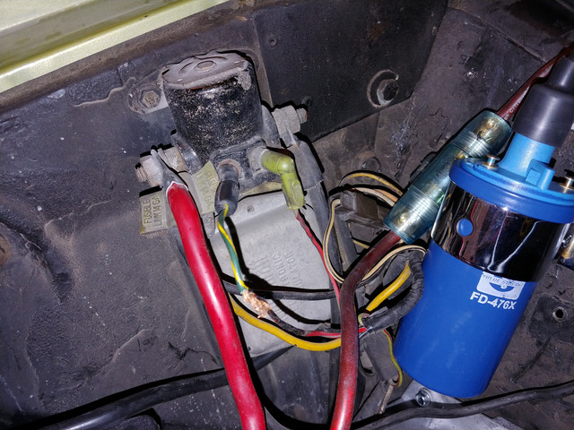
The 2 wires attached to the solenoid were there.  I unwrapped the spliced wire so I can properly connect it.  Someone previously put on a wire nut and a ton of electrical tape.

 
quick follow up: I tested the 2 wires on the passenger side manifold.  The uncovered spade gives a little north of 12v when the ignition is on (did not test crank).  The other has no voltage, so I'm assuming that's the negative.

 
The wire that originally connected to the positive side of the coil is red with a light green stripe, it connected to the pink wire inside the firewall. The wire that connects to the "S" terminal on the starter solenoid is red with a light blue stripe.

The wire that connects to the "I" terminal on the starter solenoid was also red with a light green stripe. It's function was to supply the coil with full battery voltage when craning/starting the engine.

You can't tell if the resistor wire is intact, or not, by measuring the voltage at the end of the wire that connects to the coil. The voltage reduction takes place only when the resistor wire is "loaded", that is when a load is applied to it as when the wire is connected to the coil and the negative side of the coil is grounded, either by a jumper wire or the points or electronic ignition.

Having a wire nut in an electrical circuit on a car is troubling, shows poor quality workmanship, and makes anything else they did suspect. The only place wire nuts can be used on a car is in the speaker circuits, but I won't use them, even then.

 
Last edited by a moderator:
Don -- I can't thank you enough for your help during this.  I was able to get everything wired up, and the car is running a lot better.

I ended up using the pink/red w/ green wire to trigger a 12v relay with an in-line 20amp, connected to the positive side of the starter solenoid.  I then split that to the ignition control module, and the coil.  I initially had a resistor that came with the wiring kit in-line to the coil, but the car would die after moving the ignition key from cranking to running.  I removed the resistor, and the car will stay running.

The car still needs to be timed, and since there are no timing marks on the harmonic balancer, i'll have to figure that out, but i'm a lot closer.  I also think there's an exhaust leak between the heads and exhaust manifolds.  I only think that because when accelerating, it's quite a bit louder with a sort of "popping" noise.

Thanks again for all of the help

 
Back
Top