OK, watched both videos, recocked and took another shot. In the end, it looks like two paths to arrive at the same location.
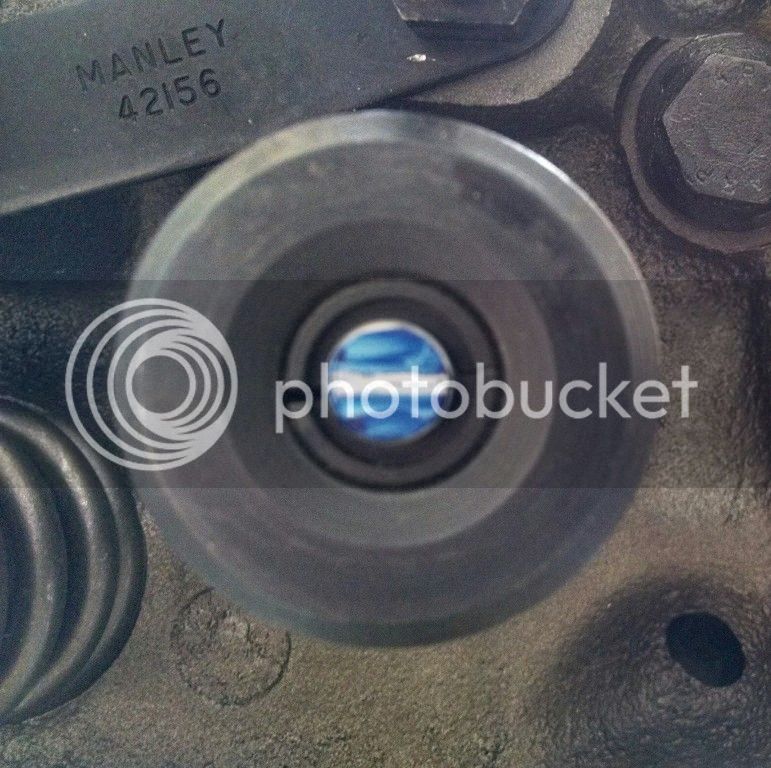
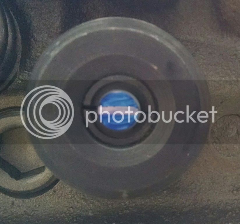
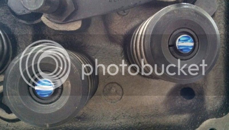
I drew the 90 deg. line on the rocker, installed at 90 deg., turned down the nut, set the pushrod, dialed to 50% lift and had the centerline as close to 90 deg. as it could possibly be. I dialed to max lift (.659/.666) on each vlave and the numbers matched the cam specs. The pushrod was the same length as I had previously established, within a couple thousandths as I measured it. It shot the same pattern on the valve stem.
I'm thinking my length is good at this point. The information was great and it was a good exercise. Is there anything I missed?