A lot of progress has been made over the last couple of days.
I ordered some more T-slot so I could drop the rear of the jig. Who would have thought that having an aluminum bar in the way of one's beer belly would have ever presented an issue?
 View attachment 92303
This made it the jig slightly less stiff than before, so I doubled up at the back, just to be on the safe side. The supports at each corner ultimately hold this thing in place anyway.
View attachment 92304
I had a hell of a time trying to get the uprights to fit yesterday. They'd slide in, but trying to blind-feel the screws into the T-slot nuts proved to be impossible. I cut the step-up adapters in length yesterday for a test fit. Today was the first try.
View attachment 92305
Spot on.
View attachment 92306
I also have a theory why the previous reading of the car's tilt was 0.2 degrees high on the right side:
View attachment 92307
I can't be 100% sure this level was the culprit, but I
think that was the gauge I used on August 10th; it has a mark on it that I believe I remember from the initial measurement.
Either way, I can always re-check to the frame, but in a way, this
is a check to the frame. I really have no doubts about the state of the frame at the front leaf mounts/behind the torque boxes and I know I have the centering spikes at the exact same height, left to right. When I leveled the car with the laser, I
nailed the bottom edge of the framerails on the horizontal line. In other words, every check has been correlating with the other - a sign that I have everything in the right place rather than the wrong place.
At the back, things are a bit more of a headscratcher.
I rough-leveled the rear of the jig by measuring from floor to T-slot. I know that's not accurate at all with all the pits in the concrete, but I wanted to get in the ballpark first; plus, I'd like to get a feel for how resilient some of these measuring points are. I set up the angle finders and tried not to look at them while I leveled out to the floor measurements - just to get an idea of how close I'd get without being influenced by their readings.
I wound up with 0.1 degree down on the left and 0.3 degrees on the right.
View attachment 92308
Not bad, but this only sets a baseline for the t-slot framing level
in space, it doesn't necessarily level it to the car. However, the car is on essentially identical jackstands front to back (with one out in front compensating for how nose-heavy it is, so it should - in theory - be close.
But the rear is
not anywhere as satisfactory as the front, and I can't explain it - yet.
This evening, I freestanded the verticals for measuring the rear, as I couldn't install them - the exhaust is in the way. I ordered some more T-slot to mount these from the outside facing in instead.
View attachment 92309
While I'm clearly in the ballpark, lengthwise (the t-slot crossmember is set to the 51.34" spring hole-to-spring hole measurement), it's not anywhere near where it should be in regards to height.
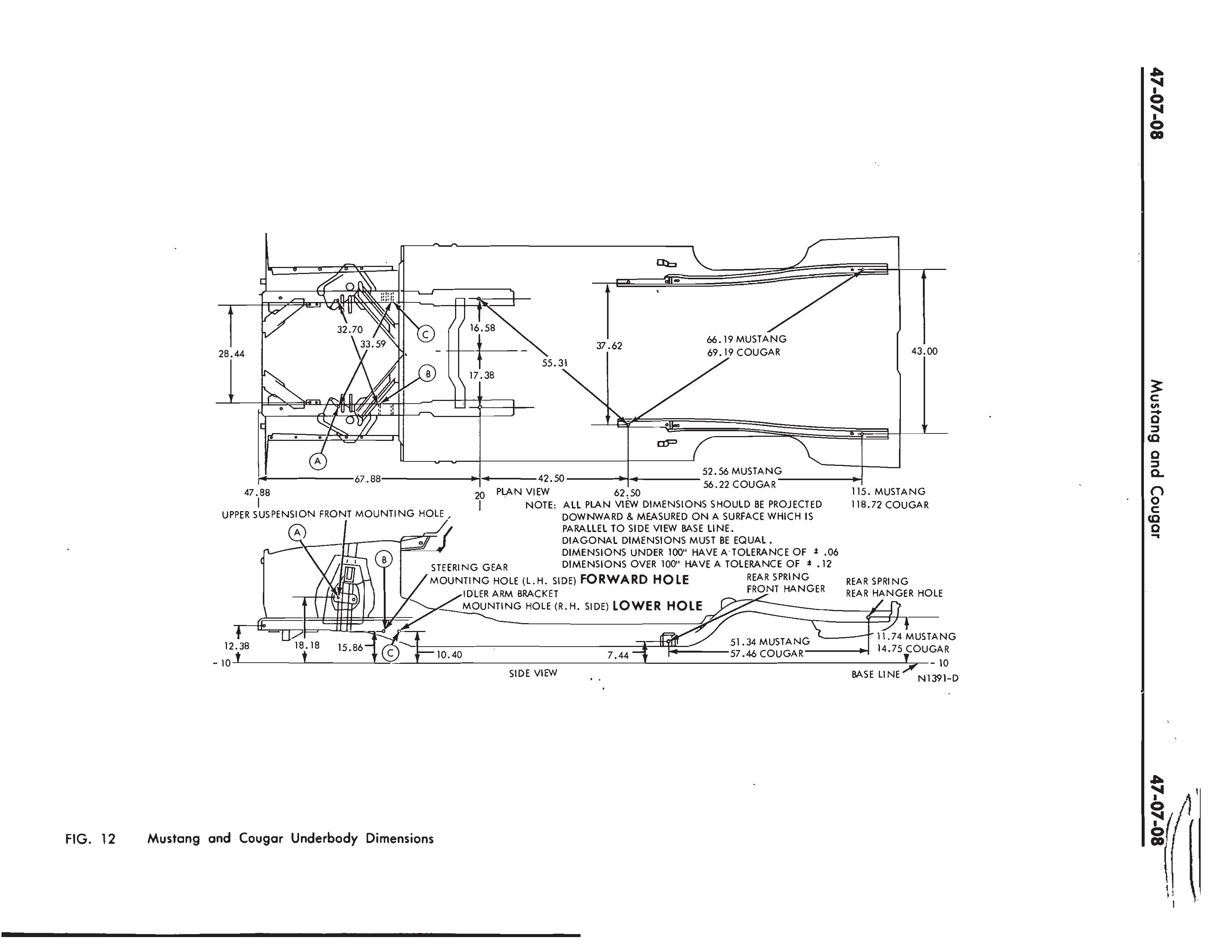
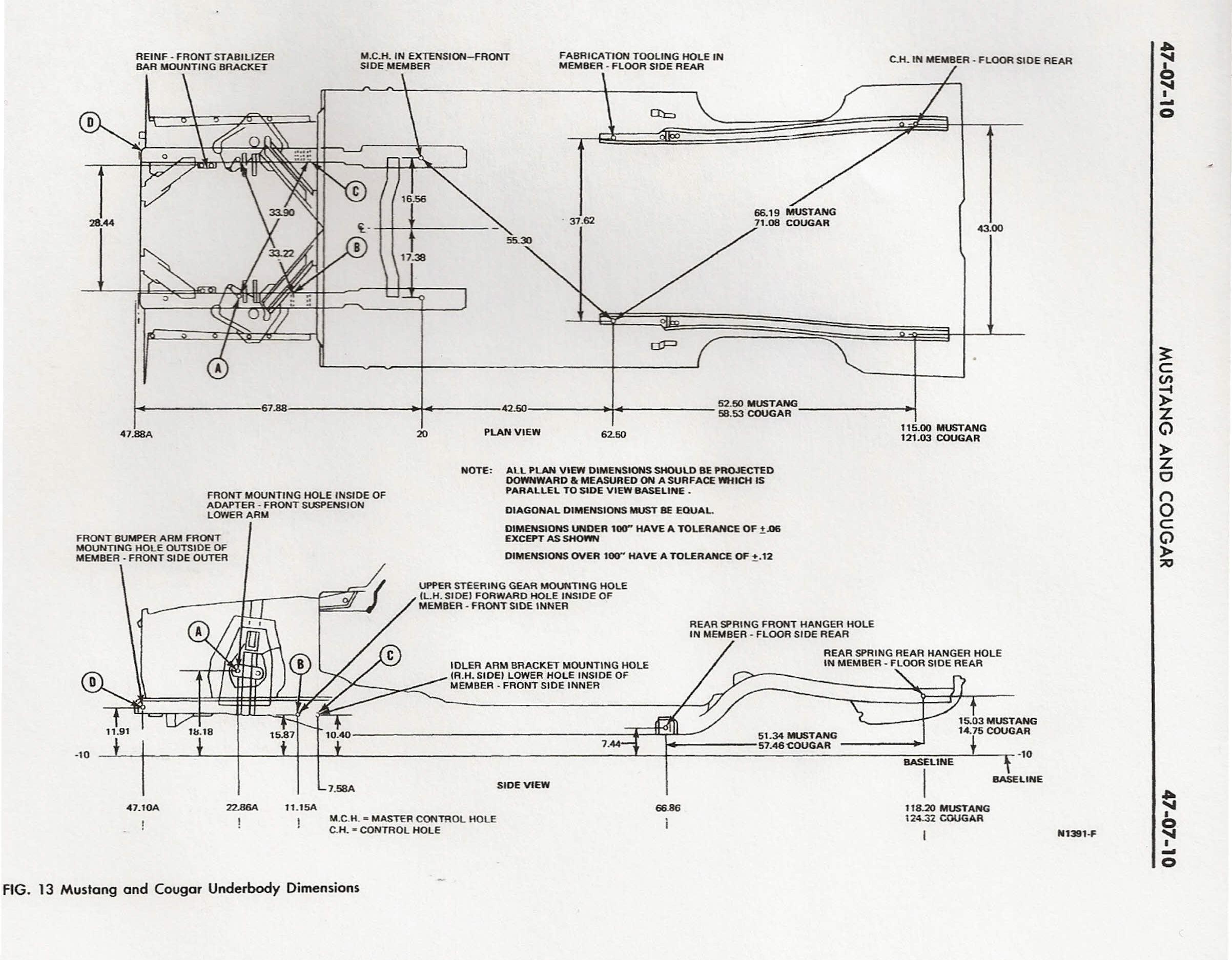
The centering spike is set here to the 15.03" measurement specified in the second factory diagram (or rather, 381.7mm; it's easier to measure this in metric when working on the car). Roughly eyeballing it after the fact, it looks somewhere
around ~3/4" too high. The alternate 11.74" measurement (from the first of the two diagrams I posted above) is clearly a typo; it'd put the framerail down into the valance if that were a valid measurement, so we can dismiss that for now. Also, if it's ~3/4" off, that would put it's current position lower than the claimed 14.75" measurement for the Cougar.
Now, the T-slot could always be angled too high in the back (it's 0.1 degree off from level here; don't recall if up or down) which would certainly contribute to this discrepancy, but I question whether the car is
that much higher in front to warrant an aggressive downwards angle of the T-slot to the back.
Once the additional T-slot arrives for the jig's "outriggers," I'm going to take some more accurate measurements of the rear shackle bushing. I'd particularly like to find out what the difference is between the 15.03" measurement and where the frame claims to be currently. I also want to find out if the car
is angled up in front, though I doubt it (and I think the next nearest point is the idler arm bolt - not ideal).
There's one other thing: I've always had a suspicion that the rear crossmember edge is sitting
higher than it should suggesting the framerail is sitting too
high - not too low - from where it should be, contrary to what the measurements suggest. You might notice in some of the older photos of the car that the lower edge of the taillight panel (where the screws for the valance go) isn't backed by the crossmember where you'd expect it to be, but sits higher than that. It's high enough that the holes in the bottom of the taillight panel completely miss the crossmember, and the recess on each side of the taillight panel for the rear bumper dips a bit below the trunk floor as well.
I'm not 100% sure if this is the way it should be - it's been a while since I've had my paws around another '71-73 - but if I recall right, the valance screws are supposed to self-tap into the crossmember.
If anyone happens has a photo of their taillight panel and rear trunk crossmember with the valance removed, it'd help out a lot. Either that, or I might have to pay a visit to
@BigBlue to check his coupe in person.
-Kurt


 .
.


