More Electrical/Idle Problems

7173Mustangs.com

Help Support 7173Mustangs.com:

This site may earn a commission from merchant affiliate links, including eBay, Amazon, and others.
I finally got my damn harness in the mail. Sooo I have 3 connectors to go on the alternator it looks like. I took it out so long ago I forgot again. Where do the orange connector and red connectors go? I think orange is Field and red is just another ground? As for the part that connects to the headlight harness, I have the green wire with the red stripe but not a yellow wire to connect to. I'm thinking that is just instrument group?


The orange/light blue wire goes to the field terminal on the alternator. The black/orange stripe wire goes to the battery terminal on the alternator. The yellow wire, at the regulator connector, goes to the static suppression/radio filter.

 
The orange/light blue wire goes to the field terminal on the alternator. The black/orange stripe wire goes to the battery terminal on the alternator. The yellow wire, at the regulator connector, goes to the static suppression/radio filter.
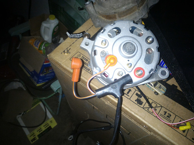
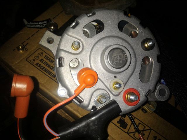
Thank you so much! I was using a diagram online but it wasn't listing everything. I'll get that stuff in there and try to crank this baby up

 
Got a new harness and alternator in there now as well as all new battery cables and a new voltage regulator. Theoretically all my wiring should be new now. However the problem still happens, but I now notice that when the headlights are on and I turn the hazards on, the pattern is slow and dims the headlights slightly. If I turn them on without the headlights on they blink faster. The car isn't stalling now but it still does surge in rpm

 
Last edited by a moderator:
What does your ammeter do when you turn both the headlights and flashers on?
It sits in the middle but with the flashers on it slightly pings to the right in unison with the flasher pattern.

 
Check the battery voltage with the engine off, with it on at idle, and with it on and idling and the headlights, flashers, and heater blower running. And then perform the last two tests with the engine running between 1,200 to 1,500 RPM.

 
Last edited by a moderator:
Check the battery voltage with the engine off, with it on at idle, and with it on and idling and the headlights, flashers, and heater blower running. And then perform the last two tests with the engine running between 1,200 to 1,500 RPM.
I got 11.9V with engine off, 16V at idle, and then when I turn everything on it switches rapidly from 16V to 14V in unison with the flashers. This is with everything on including the heater blower. With 1500 RPM it also does the same thing with 15.94V to 14.64V.

 
Last edited by a moderator:
What kind of regulator did you use? The maximum you should ever see is around 14.5 volts. Over 15 will cause damage to electrical components, including the alternator.

 
There have been a lot of issues with repops. Get an aftermarket solid state regulator.
I put in a "Standard Motor" solid state Voltage Regulator VR166. Car still does the same thing but now the voltage is 14.66V at the most when I put the engine to 1500 RPM. It still drops to 11.64V though with the flasher pattern. I get 11.98V with the car off, 12.01V with the key "on".

 
Last edited by a moderator:
I can't remember whether or not you said you have a new battery. It almost sounds like a bad cell, but you haven't mentioned anything about cranking problems.

Try this, check the voltage at the positive wire on the coil when the points are closed and the key is on. Don't leave it like this very long, or the coil will get hot. And then check it when the points are open.

What coil did you put in? I believe you said the ignition was stock, so it should be one for a ballast resistor or a resistor wire (which your car has).
I have a battery thats new and it reads 80% charge. The car fires up on the 1st crank every time. I have a new msd blaster 2 ignition coil. The voltage at the positive wire of the coil is 12V.

 
Last edited by a moderator:
OK, there's problems with catalog listings of alternator harnesses. If you have an alternator indicator lamp, you need the 4 pin used version on the voltage regulator plug.

If you have an ammeter or voltmeter, you need the 3 pin used version of the voltage regulator plug.

AMP, who makes almost all of the reproduction harnesses, screwed up the identification of these alternator harnesses. They went on the assumption that the tach dash requires the 4 pin version, which is correct for all Mustangs from 67-70. In 1971, Ford had the ammeter added to the 3 gauge cluster for the tach dash, so now the ammeter comes with the tach dash. From 67-70, the ammeter came with the non-tach dash. Everyone believes the correct harness goes with the tach dash configuration, when, in fact, it has to do with the ammeter or alternator indicator lamp. If you don't believe me, simply check your Ford Shop Manual in the Charging Section.

Corrected by Midlife.

 
Last edited by a moderator:
OK, there's problems with catalog listings of alternator harnesses.  If you have an alternator indicator lamp, you need the 3 pin used version on the voltage regulator plug.  

If you have an ammeter or voltmeter, you need the 4 pin used version of the voltage regulator plug.  

AMP, who makes almost all of the reproduction harnesses, screwed up the identification of these alternator harnesses.  They went on the assumption that the tach dash requires the 3 pin version, which is correct for all Mustangs from 67-70.  In 1971, Ford had the ammeter added to the 3 gauge cluster for the tach dash, so now the ammeter comes with the tach dash.  From 67-70, the ammeter came with the non-tach dash.  Everyone believes the correct harness goes with the tach dash configuration, when, in fact, it has to do with the ammeter or alternator indicator lamp.  If you don't believe me, simply check your Ford Shop Manual in the Charging Section.
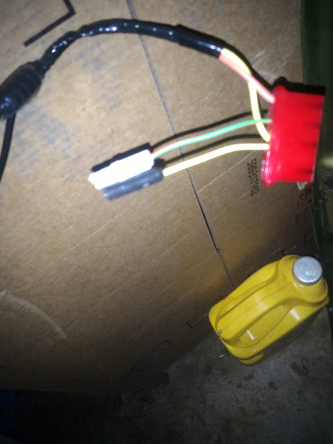
So did I get the wrong harness? I got the AMP one from CJP. https://www.cjponyparts.com/alternator-wiring-harness-w-instrument-1971/p/WALT7A/

Do you think this is causing the problems with the flashers etc? What should I do if so

 
Do you have an ammeter? I sold you a tach setup with the 3 gauge cluster, so you need the 3 pin version; what you linked to is the 3 pin version.

You need to double-check the number of pins used on your VR plug to be sure.

Corrected by Midlife

 
Last edited by a moderator:
Back
Top