Portable battery booster problem

7173Mustangs.com

Help Support 7173Mustangs.com:

This site may earn a commission from merchant affiliate links, including eBay, Amazon, and others.
Joined
Sep 12, 2015
Messages
7,662
Reaction score
2,778
Location
SW Ontario
My Car
1971 Mustang Mach 1, M code, 4 speed.
@midlife or anyone else who might know.

I thought I'd ask a quick question hoping someone is brighter than me when it come to electrical stuff.

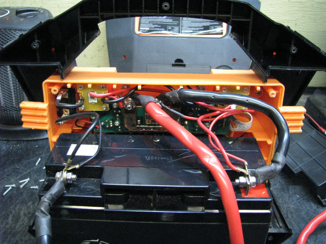
Scenario; several years ago I bought a 12V 700 cranking amp battery booster. A year or so ago, it would not take a charge, so I had the internal battery replaced. Since then, while I have kept it charged up, I have not needed to use it until today. All I needed it for was to test a Pertronix Ignitor II that was thought to be faulty right out of the box. It sat on my shelf until the warranty ran out of course. I found a video on how to test these using a booster, so I thought I'd do the same thing. Easy peasy right, no, I could not get any power from the booster box.

Question; There is no switch on this model, so should I have full 12V between the red clamp POS, and the black clamp NEG at all times? The internal battery has a full 13V, the two 12V sockets also have full power, but not across the clamps, nothing. 

I suspect the internal circuit board may be toast and that is why I'm not getting power. The accessories connect directly to the battery.

Thoughts?

I was able to test the PII using the two 12V sockets and it has a short internally. My test light should not be lit from a ground wire the module base. It should only light when the magnet passes the module sensor. I used a spare dizzy to set up the test.

Just for interest, here is the video.


I suspect that the internal circuitry detects when it's connected to a battery and that turns it on. I have a good quality battery charger that shows no voltage between the clamps, and the clamps can be touching each other with no sparks flying when the charger is turned on. As soon as it's connected to a battery it powers up (if it's turned on).

 
I suspect that the internal circuitry detects when it's connected to a battery and that turns it on. I have a good quality battery charger that shows no voltage between the clamps, and the clamps can be touching each other with no sparks flying when the charger is turned on. As soon as it's connected to a battery it powers up (if it's turned on).
That makes sense. If yours does not have power to the clamps at all times, but does when connected, that is probably why I'm thinking mine is not working. However, it would be hard to know if the booster is, connected to fully charge car battery.

No power to the clamps would be a safety measure for sure. I was also thinking that when I had the battery replaced at a battery shop, they may have connected it up wrong as there is a heavy black cable from the POS terminal to the circuit board, but without that wire in place, nothing works, so I guess it's right. There is a small red wire spliced to the heavy red cable, that most definitely looks like it was repaired, not factory looking for sure. See pic. I wonder if they took those heavy wires off the c/b and switched them around.


Thanks for your quick help.

 
I believe it is wired correctly. The black cable that is connected to the positive side of the battery runs to the circuit board and the red cable runs from the circuit board to the positive clamp. They are likely connected together with a solid state switch when conditions are right.

 
I believe it is wired correctly. The black cable that is connected to the positive side of the battery runs to the circuit board and the red cable runs from the circuit board to the positive clamp. They are likely connected together with a solid state switch when conditions are right.
Thanks Don, kind of what I thought it might be, after all there would be no need to unscrew those internal terminals just to change a battery, but I'm curious how the small red wire got broken and repaired (and not very well). It just struck me funny that there would be a black covered wire on a POS terminal.

I appreciate your input,

 
Hi guys -- one possible check is make a dummy load. 

These products are likely to be "load dependent" circuits that detect the input impedance of the vehicle circuit.

This is a safety feature to save the owner from getting a huge DC flash-over ( would look like a big welding arc) in the face if they hooked that "super-capacitor" to a shorted cell or the output leads came together.

Unless you can make up the full car circuit, out of old kit lying around your garage, on the bench with battery, starter solenoid and starter motor. 

One way to trick it is with a bit of ohms law to make a "dummy load" out of a few resistors. 

I'd pull a sensible/practical currant rather than the full 300A. If you can pull say 25A from it (most people have cable in their garage that can handle 25A) ... I'd be pretty satisfied that the unit can hold charge. Switch the load in for only short periods as the load will get hot.

V/I = R 

12/25= 0.48

closest commercially available value would be 0.5 Ohms 

2x 1.5 Ohm + 1x 1 Ohm resistors in parallel gives you that value plus the Wattage capacity to accept it. assuming 100Watt armored resistors are used. 

and put an analyzer in the way https://www.ebay.com/itm/Digital-Monitor-LCD-Watt-Meter-DC-Ammeter-RC-Battery-Power-Volt-Amp-Analyzer-Car/264589952225 


Last edited by a moderator:
Hi guys -- one possible check is make a dummy load. 

These products are likely to be "load dependent" circuits that detect the input impedance of the vehicle circuit.

This is a safety feature to save the owner from getting a huge DC flash-over ( would look like a big welding arc) in the face if they hooked that "super-capacitor" to a shorted cell or the output leads came together.

Unless you can make up the full car circuit, out of old kit lying around your garage, on the bench with battery, starter solenoid and starter motor. 

One way to trick it is with a bit of ohms law to make a "dummy load" out of a few resistors. 

I'd pull a sensible/practical currant rather than the full 300A. If you can pull say 25A from it (most people have cable in their garage that can handle 25A) ... I'd be pretty satisfied that the unit can hold charge. Switch the load in for only short periods as the load will get hot.

V/I = R 

12/25= 0.48

closest commercially available value would be 0.5 Ohms 

2x 1.5 Ohm + 1x 1 Ohm resistors in parallel gives you that value plus the Wattage capacity to accept it. assuming 100Watt armored resistors are used. 

and put an analyzer in the way https://www.ebay.com/itm/Digital-Monitor-LCD-Watt-Meter-DC-Ammeter-RC-Battery-Power-Volt-Amp-Analyzer-Car/264589952225 

 Thank you for your electrical insight. Way above my pay grade though. Anyway that information might be very helpful to others who understand electrical systems. For now, I am confident I understand why I did not get any power through the cables. It makes perfect sense now.

As I mentioned upfront, my aim was to test a Pertronix Ignitor II that, although brand new never been out the box, did not work when I thought my installed one was failing. I was able to find it obviously has a short of some sort as the test light came on through the ground wire, (sorry, earth wire). It should not have according to the video guy.

Thanks again and I appreciate your input.

Geoff.

PS, unfortunately that ebay unit cannot for some reason be, sent to Canada.

 
You might try one of these

https://www.harborfreight.com/100a-612v-battery-load-tester-61747.html

Inexpensive way to see if a resistive load will turn it on.
Don thanks, I'll earmark that for sure for next time I'm "allowed" to travel to the US! I may be able to find one similar on Aamzon.ca for a reasonable dollar. For now, I'm going to put the booster back together and back on the shelf. I was able to test that module and it's f'd which is too bad, just another 200 bucks Cad down the drain.

 
or just leave the headlights turned on in you're wife's car overnight to drain the battery and then see if it works. :)
Hmmm! that would go over REALLY well!! I think I'll take my chances, put it back together and try Don's suggestion. I might live a little longer.

 
Back
Top