sequencial turn signal project

7173Mustangs.com

Help Support 7173Mustangs.com:

This site may earn a commission from merchant affiliate links, including eBay, Amazon, and others.
I think we should get some info from "TheJ" on his LED setup he is doing.

the New Mustangs have red and white LED's mixed and when you press on the brake all 3 light up, but when you press on the brake while in reverse the center section stays white while the 2 outer section are red.

then with the bilkers they are sequential, but when you press on the brake they are steady red.


Last edited by a moderator:
That's a great idea Iyman.Thanks for the new feedback as well.

To be honest, i've lost contact and haven't kept up with what The J is doing with Obsidian's new tailights.

Maybe a PM to get some feedback as well.

Greg.:)

 
Last edited by a moderator:
I think we should get some info from "TheJ" on his LED setup he is doing.

the New Mustangs have red and white LED's mixed and when you press on the brake all 3 light up, but when you press on the brake while in reverse the center section stays white while the 2 outer section are red.

then with the bilkers they are sequential, but when you press on the brake they are steady red.
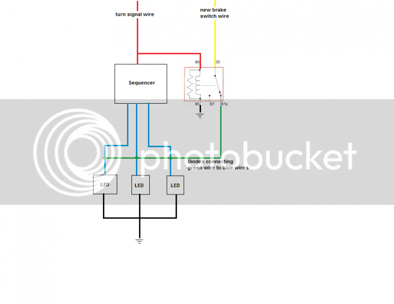
Honestly, the way I was planing on doing it would required running a separate wire to the brake switch because I can't figure out how to do it another way. This is because of the way the cars are wired, the brake wire runs through the signal switch meaning when the switch is open (not signaling left or right) 12v is provided constantly to the 1157 bulbs. When the switch is turned to signal it breaks the 12v from the brake switch and provides and on-off-on... signal from the flasher to the 1157 bulbs. There has to be some sort of logic chip that is programed to recognize constant on vs on-off-on.. and output accordingly but that exceeds my electronic knowledge at the moment.

Sorry I couldn't be of more help but hopefully that makes sense.


As for the LEDs for Obsidian's tail lights, I injured my and a few weeks back and have been really busy playing catch up since I've been able to use it again. I will try to get an update on them by next weekend.

 
Last edited by a moderator:
Jayson, I was thinking of having the logic chip in the trunk, where the wiring splits to the light fixtures

if it receives one signal (left or right) which is the LG-O wire or the O-LB wires then go to the sequential circuits for the blinkers, and if it receives a signal on both right and left (LG-O and O-LB) then bypass the sequential circuits and go directly to the lights for the brakes.

let me know if you think that will work.

if so let me know, and I can draw up a schematic, or I can make a test using electronics workbench.

 
I think that would work I just don't know of an IC chip that differentiates between inputs. With the sequencing circuit I'm using under braking it would only sequence once when you initially hit the brake then it would be constantly on, while kind of annoying it would still function well as a brake light.

 
or instead of getting too complex, your idea of running a separate line for the brake and bypass the sequential circuit.

I found this sequencer online for $300 and that's what it does.

$(KGrHqN,!gsE5tMu,cSQBOvY-qU!cg~~60_3.jpg

$(KGrHqIOKm8E6HViZe-VBOvZ90WDow~~60_3.jpg

$(KGrHqV,!jME66MHip4uBO2GOPtLwQ~~60_3.jpg

 
This is pretty much the simplest and most dependable way I've figured to do it.


This requires running a separate wire from the brake switch and unplugging/depinning the existing one.

Hopefully my schematic makes sense.

 
Last edited by a moderator:
Greg, i'm not sure how these are set up. I have been looking at them and thinking about it...if they used red LED's in the center it would work for the backup lens area but, I was worried about a weak illumines behind the red lens, if they mixed them I would think the white LED's would bleed through...maybe a phone call to them would clarify our questions. In my opinion, a simple plug and play like this would be worth the money to get 3 lens sequential turn signals, and keep the backup where it is, with LED's to boot.
I agree with what you say here Wendell. Over the next few days, i'll find time to ring the company in America, and see if i can learn more about this product and how it functions. I'll stay posted in that regard.

BTW - I'm a crazy music man myself. I play, collect, and do some light engineering with music as mainstream activity. I got into decent home Hi-Fi back in 1976, and am still with it. My weapon of choice has always been Yamaha Hi -Fi over the years and i got into Yamaha Home Theatre back in 1992.

Sounds like you and me could spend countless hours disscussing matters music.

Cheers mate,

Greg.:)
76-79 were great years for HiFi. Yamaha, Sansui, Kenwood, and many others produced some great sounding units back then

 
This is pretty much the simplest and most dependable way I've figured to do it.

This requires running a separate wire from the brake switch and unplugging/depinning the existing one.

Hopefully my schematic makes sense.
this makes perfect sense, and you are right, its the easiest way to do this and it is dependable.

 
HMMMM??? I bought a kit from this site for my 03 GT. Maybe, somehow we could use parts to help us make our 123's all three flash? Or at least get some ideas.

http://www.sequentialtaillights.com/mustang.html
Just wanted to give an update on your contact. I Emailed them and got this response back.......................

Well Hello Mr. Greg!

Nice to hear from someone down under! I do not have any hardware that would adapt to your model

Mustang, as you have the smaller split taillight with the brake light in the center piece? If I were you

and you wanted to go to the Cobra style taillights that some have gone to, you then will have a light

bar that can be sequenced like this chap here in this video. Note the end of the video where the

driver cycles through the left and right turn signals near the end of the timeline (about 1:30).

This can be done to your vehicle I believe.

http://www.youtube.com/watch?v=OJtIbJvBPUQ

-Marv'

As you can see, this lead is best described as a dead end, but i do thank you for putting it forward.

Greg.:)

 
This is pretty much the simplest and most dependable way I've figured to do it.

This requires running a separate wire from the brake switch and unplugging/depinning the existing one.

Hopefully my schematic makes sense.
this makes perfect sense, and you are right, its the easiest way to do this and it is dependable.
Hey Iyman,

It will be interesting to see what you might come up with if you are keen or interested enough to make a working saleable product.The balls in your court i guess. Best of luck with it all if you proceed.

Greg.:)

 
This is pretty much the simplest and most dependable way I've figured to do it.

This requires running a separate wire from the brake switch and unplugging/depinning the existing one.

Hopefully my schematic makes sense.
I agree, this will work fine and is the simplest solution, although requiring someone to run the separate wire and figuring out how to disable the existing brake light circuit. An alternative is called a 2 to 3 wire converter and is used for pulling a car with separate brake/turn signal lights by a motorhome with the single filament for stop/turn signal bulbs.

I've installed them on three different "toads" and they work well. I've also tried to come up with a schematic for them for years without any luck,and I've been reluctant to take a new one apart just to see how it works.

Here's an example, they're not expensive, but would add to the overall cost and involve having another device that could fail someday:

http://www.etrailer.com/Accessories-and-Parts/Curt/C56196.html
That's cool, I'll look into these. Thanks for the info and link.

 
Back
Top