Vacuum hose routing

7173Mustangs.com

Help Support 7173Mustangs.com:

This site may earn a commission from merchant affiliate links, including eBay, Amazon, and others.
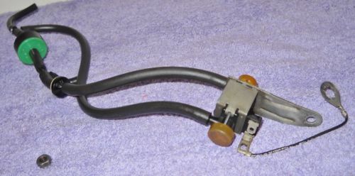
Omigosh, thank you -- Haven't examined closely (project a bit on hold until after Xmas), but at first glance... you may have found it!

 
I still would not take this as being 100% accurate or complete. Just more data to add to the mix. Some things still don't look quite right to me. The wire harness for the 351c-2V looks off, the air cleaners don't look right, the big knot of hoses at the rear of the 4V/MT, and probable more. Add this to Don's calibration drawings and then add the electrical diagrams and harness.........and just maybe?

 
I ordered from CJP the "Distributor Vacuum Set" of hoses for the 351-C engine (four hoses).  Lo and behold, it came with a diagram.  Nope, it's not *all* the vacuum going on under the hood, but it is pretty close to my distributor configuration.  I'm gonna give it a try.

1973 Mustang Vacuum from CJP.jpg

 
Last edited by a moderator:
I ordered from CJP the "Distributor Vacuum Set" of hoses for the 351-C engine (four hoses). Lo and behold, it came with a diagram. Nope, it's not *all* the vacuum going on under the hood, but it is pretty close to my distributor configuration. I'm gonna give it a try.

View attachment 50320
This thread has been very helpful to me in my project. Much appreciate all the work you've done and especially kingb1973. I have the exact same situation that you started with and have been trying to determine how to connect vacuum lines with our 2-port & 3-port vac switches properly. Also, like you my 73Q-code does not have the #5 solenoid valve shown in 3-14A. The marked up drawing that "kingb1973" makes the most sense to me for hose routing and I'm curious if that's what you ended up using in the end, and if so how happy are you with your engine's performance?
 

Attachments

  • Possible-Vac-Lines 1973 351-4v CJ Auto Trans 3-16A Markup.jpg
    Possible-Vac-Lines 1973 351-4v CJ Auto Trans 3-16A Markup.jpg
    1.9 MB · Views: 3
I did use that configuration which worked out great and haven't had to think about it since. But thanks for the reminder, and thanks to KingB1973
 
I did use that configuration which worked out great and haven't had to think about it since. But thanks for the reminder, and thanks to KingB1973
That's really great news, and thank you again for sorting all of this out and sharing your journey on our forum. You guys have set me up for success!
Bob
 
The 1973 Shop Manual for Emission Control (Volume 6) from Forel did not include two vacuum calibrations. They were for the 1973 351 4v engine calibrations, of course. Somewhere along the way I came across both of them, and added them to my Shop Manual pdf file, and kept copies of both the calibrations in a separate pdf file. You can get those calibrations (3-15A & 3-16A at the end of the PDF) for 1973 351 4v engines at the following link:

https://drive.google.com/file/d/1KaPP4koJHvA5a9oZ3OcuiaTCE-Z4nqaI/view?usp=drive_link


I hope that helps clear things up a bit.

Ciao!
Thanks for this. I've seen your 3-16A in other threads and appreciate you sharing it. You are right it's not in my Forel or actual hardcopy manuals either. But this doesn't match my 351c-4v. I have two Ported Vacuum Switches. One is a two port, that mounts on a special "H" shaped connector between the two heater hoses coming out of the water pump and engine block. The other is a three port that mounts to the water pump and it's vacuum is tied to the Distributor advance. "Kingb1973" came up with a marked up version of the 3-16A that makes the most sense with all the emissions stuff on this car (see post #43 above). It would be great if Ford actually had some drawings that covered this case, but I'm at a loss. I've wondered if it might have something to do with how late in the production run for the 1973 cars might have something to do with it. My car was built on 5-21-1973, so kinda towards the end. I'm guessing that the learning curve for all these added configurations to deal with the new emissions stuff made it a moving target for them at the time???

Thanks for all of your help by the way on this forum. You are great help for us all!
Bob
Having little but my own observations, I concur with the later build dates (mine was 5/4/73 - bd was yesterday!) leading to the lack of documentation.
 
Having little but my own observations, I concur with the later build dates (mine was 5/4/73 - bd was yesterday!) leading to the lack of documentation.
Well happy belated birthday to your baby! That’s a great data point that your car too was towards the end of the production run of our generation 1 cars. Like you I’m fairly certain that my car was built the way we found it. It's been in our family for 49 of it's 51 year life & no one recalls messing with any of this stuff. With all the info that "kingb1973" provided on this thread perhaps he's another one of the later production run 73s?

Here’s another example that adds to the story of “what’s right”? All the emissions calibrations (including the 3-16A) show the “normally open EGR cutout solenoid” right? If looking for a replacement Engine Gauge Feed harness (14289) for our cars I think we'd be toast too. I'm not looking for one, but just went down this path trying to look for answers. In an earlier post in this thread by kingb1973, laid out his harness & numbered the 9 connectors. It's exactly the same as yours & mine. It has the two connectors for the EGR Cutout solenoid.

NPD lists several of these harnesses, with year/configurations applicability. The one they list for our 1973 Mustang 351C-4v AT, is part number 14289-8CA. If the picture is correct, it's missing the EGR Cutout Solenoid wires, and only shows 7 connectors. The harness ID tag on my car shows: D3ZB-14289-CD. The NPD reference number for this part is D3ZZ-14289-C. So not knowing the relationship on Part vs Engineering number in this case, it does appear that our 351C-4v A/T with Air does have a different version of what's available for a replacement.

But the NPD harness does have the connector for Spark Delay Solenoid #5, which our cars also did not have? It's just puzzling, but bottom line this thread helped me greatly.

Thanks again for your work on this....Bob
 

Attachments

  • Engine Gauge Feed Wiring Harness-14289 Described.pdf
    332.5 KB · Views: 1
  • Engine Gauge Feed Wiring Harness-14289.pdf
    240.1 KB · Views: 1
Thanks for this. I've seen your 3-16A in other threads and appreciate you sharing it. You are right it's not in my Forel or actual hardcopy manuals either. But this doesn't match my 351c-4v. I have two Ported Vacuum Switches. One is a two port, that mounts on a special "H" shaped connector between the two heater hoses coming out of the water pump and engine block. The other is a three port that mounts to the water pump and it's vacuum is tied to the Distributor advance. "Kingb1973" came up with a marked up version of the 3-16A that makes the most sense with all the emissions stuff on this car (see post #43 above). It would be great if Ford actually had some drawings that covered this case, but I'm at a loss. I've wondered if it might have something to do with how late in the production run for the 1973 cars might have something to do with it. My car was built on 5-21-1973, so kinda towards the end. I'm guessing that the learning curve for all these added configurations to deal with the new emissions stuff made it a moving target for them at the time???

Thanks for all of your help by the way on this forum. You are great help for us all!
Bob
Hi! I am going to grab the info shared by Kingb1973 and add it to my little library. Thanks for the Heads Up re: differences you have and the Kingb1973 info. And, I am happy you have found some of my other posts useful. I do try to pipe up when I feel I have something useful to share. Otherwise a lot of posts are answered so well by others that for me to chime in could just confuse things. I so much enjoy working on our vintage Mustangs and Shelby. This is such a good group of fellow enthusiasts...
 
***All, Thanks for the "Shout-Outs"***
I had to go back and read the thread to see what the heck I was talking about. I have a "mid year" build. 02/73, 351C-4 BBL, MT. Have had her since she was 7 years old, but by then she had a Holley carb and most vac lines were disconnected. My research was due to the fact that I was putting a original carb back on and was trying to figure out what I needed to do.
Glad my research, although "sketchy", was a little helpful. You know what they say about blind squirrels.

RC92234-I am glad it worked out.
Moderator73-Hope it works out.
mrgmhale-A privilege to be included in your "little library" of information, although I could be all just conjecture and (WAG) wild assed guess on my part.
 
I stand corrected. Happens too often. The diagrams I have do name the 2 port unit as a Temp Control Vac Valve and not a PVS. You are also correct that with my having a Manual Transmission, I do not use/have either of the solenoid valves, but use the DVAC (#17 for 3-15A).

A pic that may help, but from a 351c-2V and not a 4V. (#5 for 3-14A config mounted on the valve cover). Note that Vac lines showing are not correct and simply looped around.

JUST READ YOUR EDIT-----------

Being you have a Q code, is it possible that you should use config 3-16A and not have/need a PVS or the #5 sol. valve, Etc.? Your valve cover decal pic shows 16A in the upper right corner. Maybe earlier in it's life the PVS was added to plug the threaded hole in the water pump? I have a plug in mine.


Hi all, is this the Spark Delay Valve Bypass Solenoid, or which solenoid is this exactly? I'm wondering if it's necessary for my 73 351C 2V Mach AT/AIR?

Thanks Ben
 
Hi all, is this the Spark Delay Valve Bypass Solenoid, or which solenoid is this exactly? I'm wondering if it's necessary for my 73 351C 2V Mach AT/AIR?

Thanks Ben

The vacuum diagram 3-14A was closest to my engine, except for mine not having the #5 Normally Open Solenoid Valve. There are both a check valve and spark delay valve in that vacuum circuit, which of course I also don't have. That might be what you're talking about?

View attachment 1973 Vacuum Hose Diagrams 3-14A.jpg
 
yes the diagram is closest to my engine but I am confused to the max because I very rarely recognize these parts on newly remanufactured engines. Conversely, does that mean I don't necessarily need them if I can't find them as reproductions? I also still can't recognize which parts were installed on which engines in which years. That would be extremely helpful. For example, in my case the 351C 2V H-Code. How do I know what valves were fitted to an AT/Air in 1973 and what was not? I'm totally at a loss...
 
The 1973 Shop Manual for Emission Control (Volume 6) from Forel did not include two vacuum calibrations. They were for the 1973 351 4v engine calibrations, of course. Somewhere along the way I came across both of them, and added them to my Shop Manual pdf file, and kept copies of both the calibrations in a separate pdf file. You can get those calibrations (3-15A & 3-16A at the end of the PDF) for 1973 351 4v engines at the following link:

https://drive.google.com/file/d/1KaPP4koJHvA5a9oZ3OcuiaTCE-Z4nqaI/view?usp=drive_link


I hope that helps clear things up a bit.

Ciao!
Thank you very much for the info!
I have a 73 Mach1 with the 351 CJ, manual transmission and no air. Calibration number 15A. As you stated, that calibration number is not in Vol 6 of the Shop Manual. I went to the dealership back in the early 80s to see if they had any additional info, but no luck. I was lucky to have all the original parts and was able to deduce the hose routing from other information.
 

Latest posts

Back
Top