I know this thread is old as dirt, but having dealt with this upgrade on other vehicles I have had, I feel I can add one more step that will simplify things.
This will go hand in hand with upgrading to a 3g Alternator, so bear in mind that is why I am wiring it the way I am.
Starting with the original wiring........

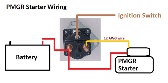
The "S" Terminal on the original is the trigger when the key is turned to start to trigger the starter.
The "I" Terminal is for vehicles that used a resistor in the primary power circuit to the coil to lower the voltage. The "I" Terminal wire will NOT be used, so it can be removed or terminated and strapped out of sight.
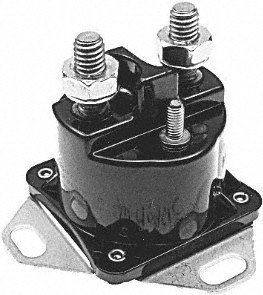
The thing I have done differently is, I take the original stock starter solenoid (fender mounted) and throw it as far as I can. Then I replace it with a newer Motorcraft SW-1951C starter relay.
Drill new holes to mount the new starter relay. Before mounting, scuff the paint off of the area where the back plate will contact the fender to ensure it gets a good ground. Make sure the screws you use firmly hold the relay to the fender. If your grounding wire from your battery is not directly grounded to the fender, run a #8 or larger ground wire to the fender near to the new starter relay or mount it directly to one of the starter relay ground screws.
If your concerned about leaving a scuffed area under the starter relay, use conductive paint to seal it. such as Bare Conductive paint.

found on Amazon.
https://www.amazon.com/Bare-Conductive-Electric-Paint-10ml/dp/B00B888LQ8/ref=sr_1_1?ie=UTF8&qid=1499549696&sr=8-1&keywords=electrically+conductive+paint
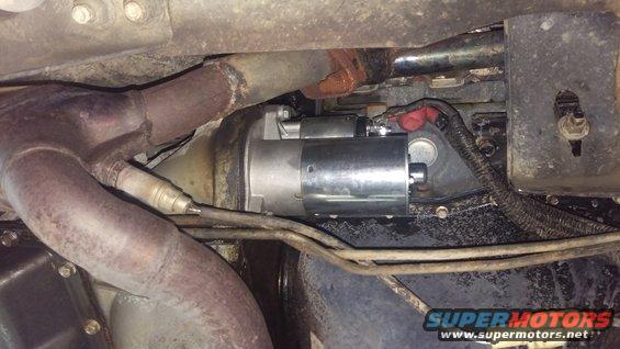
The PMGR Style Starter has 2 wires, the Power Wire, and the Trigger wire. The trigger wire takes the place of the "Solenoid" on the fender. The new style solenoid is actually just a relay, so we now call it a starter RELAY. The solenoid is now on the starter.
The alternator output of your New 3g Alternator will go to the Large Post closest to the Radiator. Also on this bolt will be all power connections for the vehicle and the battery lead.
The starter Trigger wire will go on the other Large Bolt post. This will be the only wire on that post. This wire goes to the Solenoid on the PMGR Starter.
The "S" wire from your original Starter Solenoid will go on the top center post.
If you use a 3g Alternator with a built in Self Exciter you dont even need to provide a 12v exciter wire to the alternator.
This is the alternator I am getting for my mustang. It already comes with a billet V belt pulley attached and all the clearancing work done for the pulley.
http://www.ebay.com/itm/100-NEW-ALTERNATOR-FORD-MUSTANG-1965-96-HOT-ROD-BILLET-PULLEY-1-ONE-WIRE-130AMP/290788756441?ssPageName=STRK%3AMEBIDX%3AIT&_trksid=p2055119.m1438.l2649


Notice it only has 2 wires on the 3g Plug. Since it doesnt need the 12v exciter wire it was removed. This way the only wire you need is the power feed wire. Use a suitable mega fuse in the line between the alternator and the starter relay. I would go with at least a 2 gauge wire with solder on terminals. When I did this on my Bronco, I used #1 AWG Wire and solder on terminals for everything.
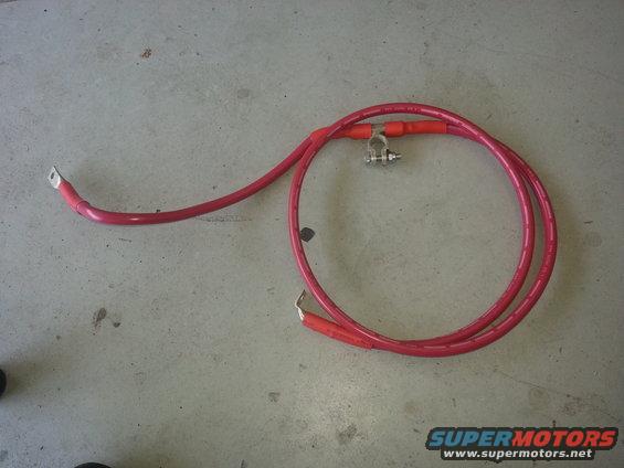
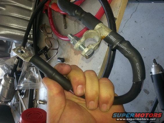
Your main Positive Battery Cable will need to use a Flag Terminal. One leg of the Flag Terminal will go to the Power side of the starter Relay (Closest to the radiator). The other side of the Flag will go directly to the Starter Power Connection. This way the starter gets direct to the battery without any other connections to reduce the power flow.
I would also suggest using a Flag Style Terminal on the Ground Lug of the battery.
One Side will be your Fender Ground. The Other side will go to your Engine Block, then a Jumper Over to the Front K Member Ground.
Note that #1 AWG Wire is pretty stout. This was in my Bronco where I have a 230A Alternator, so the wires wont need to be that large unless your going to run a 1500w Stereo.
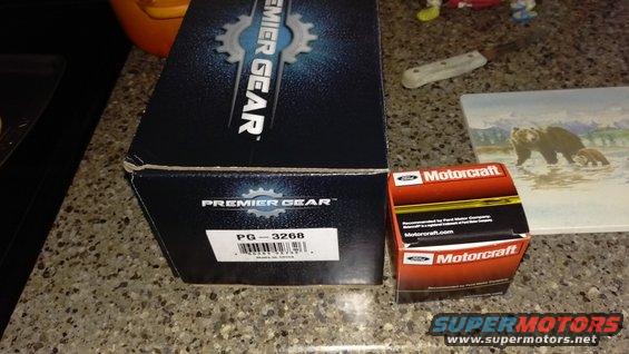
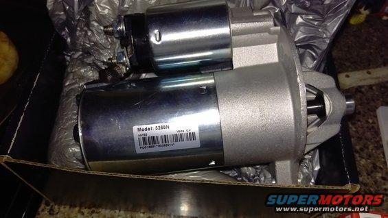
I used this Premier Gear PG-3268 Starter I got from Amazon for about $65. Its been great the last couple of years.
https://www.amazon.com/Premier-Gear-PG-3268-Professional-Starter/dp/B00KY0MPH2/ref=sr_1_1?ie=UTF8&qid=1499550888&sr=8-1&keywords=PG-3268
Well thats about all I have to add.
Just dont Forget to rip out that old External Voltage regulator and chunk it in the trash next to the old starter solenoid. You will still need to do something about your ammeter gauge, so keep that in mind. Converting it to a volt meter is the way to go, then you can tie it in with all the other power wires on the relay and get accurate charge voltage readings. I would suggest trying to find an aftermarket gauge though, so you know what your looking at, unless you just cant deal with it, then go with the rocketman mod gauge.


")