- Joined
- Apr 27, 2012
- Messages
- 4,766
- Reaction score
- 107
- Location
- Nashville, Tennessee
- My Car
- 1973 Q code Mach 1
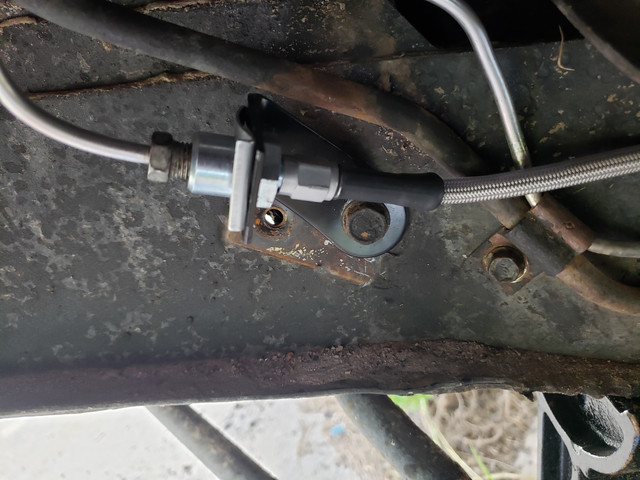
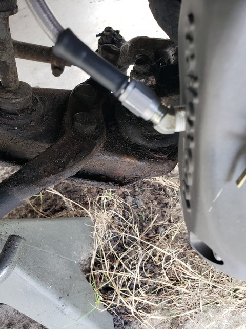
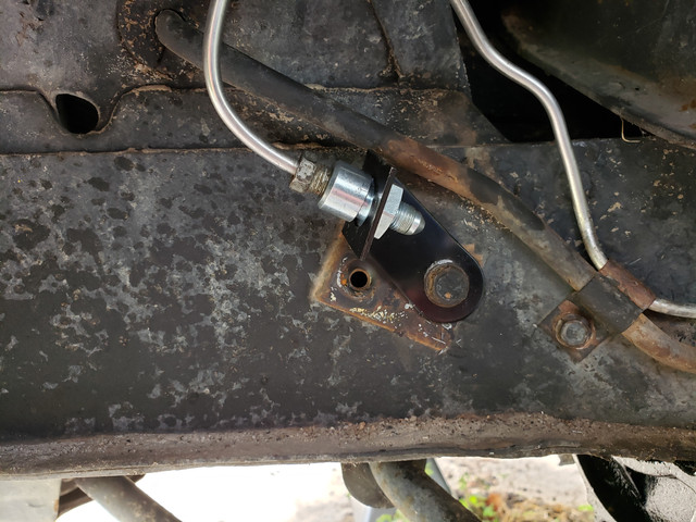
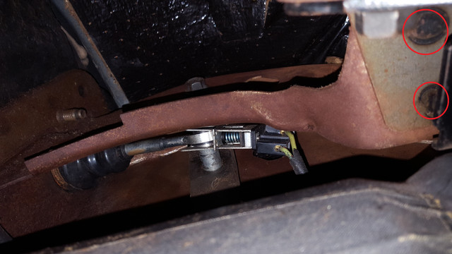
As long as the brake line sits in a safe position throughout the range of travel and suspension movement and the bleeder valve is at the top of the caliper, front or rear positioning is fairly unimportant.


")