Wiring problems Tachometer Mustang -73

7173Mustangs.com

Help Support 7173Mustangs.com:

This site may earn a commission from merchant affiliate links, including eBay, Amazon, and others.

nursieee

Well-known member
Joined
Dec 8, 2019
Messages
68
Reaction score
2
Location
Sweden
My Car
Ford Mustang Fastback Mach 1 1973
Hi have my first mustang and im trying to fix it, got some problems with Tachometer for a start.

Tachometer doesn't work and never did. I did check the wiring so i think i got that right. When i run the engine, I measure about 12 v in to the tachometer and 12 v out and still it don't work? Is that how it should be? According to the wiring diagram there should be some kind of resistor between the firewall and the tachometer. I cannot find, it what is it, how does it look?

Is it the tachometer that is broke or could it be something else that's wrong?

 
Last edited by a moderator:
I believe you are troubleshooting it correctly. There's two possibilities, either the tachometer has failed or the previous owner bypassed the tachometer and resistor wire.

The resistor is a wire under the dash, and is between the tachometer and the dash. It is pink and has something like "Do Not Cut" written on it.

If the tachometer has failed your best option may be to have Rocketman, a forum advertiser and supporter, rebuild and modify your tachometer so it works like a modern three-wire tachometer: https://www.rccinnovations.com/

 
I believe you are troubleshooting it correctly. There's two possibilities, either the tachometer has failed or the previous owner bypassed the tachometer and resistor wire.

The resistor is a wire under the dash, and is between the tachometer and the dash. It is pink and has something like "Do Not Cut" written on it.

If the tachometer has failed your best option may be to have Rocketman, a forum advertiser and supporter, rebuild and modify your tachometer so it works like a modern three-wire tachometer:  https://www.rccinnovations.com/
Ok i´ll look for that cable or is it possible to connect a new resistor and if so which Ohm should it be? and also dont know if this tells anything, but the lights in the gauge panel doesnt work either?

 
If the engine runs and the tachometer doesn't work, either the tachometer is bad or has been bypassed. If the resistor wire is bad the engine won't run, unless it has been bypassed.

By the way, please go to the introduction section of the forum and introduce yourself and your car. A few pictures of your car would be nice, too.
Now there is some pics of the Mustang. 

My idea is to put a resistor between the ignition coil and the tachometer on a new cable, just to see if the tachometer works. Im not sure how many ohms it should be. I did read 1,5 ohm anyone who can confirm that?

 
I have the same issue, can't get the tach to work and I know nothing about wiring, lol. I tried three different tachs and my car does have MSD ignition and I got their tach adapter and still does not work. It is a car that did not come with tach but I changed the harness from the headlights to the fuse box and all under dash wiring. Everything else works, key buzzer, seat belts and all but no tach. 

Which a tach is a pretty useless thing unless you are drag racing and use it to stage. You change gears when it quits pulling no matter what RPM. It just looks cool, lol.

Will watch you post to see if I can learn something about this. I have 6 mustangs with factory tach and one parts car with. But only two of them running now.

 
The resistor wire should be about 1.5 ohms. If it is bypassed the tach will read high until the tach dies (too much current = shortened life span). If you add more resistance the tach will read low.

The tach can fail on the electrical or mechanical side. The movement (mechanical) is normally pretty solid, but in'71 Ford switched from Bendix to Faria as a tach supplier. You can guess why... "lowest bidder".

The Faria tach movements have stacked magnets that were epoxied together and tend to dry out and fall apart. They also used plastic internals that tend to dry out and crack or break. To put it nicely Faria products were (and still are) junk.

The electrical side is the most common failure though. Depending on what wears out and fails the car may or may not run with a dead tach.

 
The resistor wire should be about 1.5 ohms.  If it is bypassed the tach will read high until the tach dies (too much current = shortened life span). If you add more resistance the tach will read low.

The tach can fail on the electrical or mechanical side. The movement (mechanical) is normally pretty solid, but in'71 Ford switched from Bendix to Faria as a tach supplier. You can guess why... "lowest bidder".

The Faria tach movements have stacked magnets that were epoxied together and tend to dry out and fall apart. They also used plastic internals that tend to dry out and crack or break. To put it nicely Faria products were (and still are) junk.

The electrical side is the most common failure though. Depending on what wears out and fails the car may or may not run with a dead tach.
Ok thanks, i uncovered the harness between the firewall and the tachometer and didnt find any pink cable anywhere. So im hoping a resistor of 1,5 ohm will help.

By the way i noticed that the lights in tach house, gas gauge, or speed gauge work i.e the whole gauge house dont work and i checked them they are not broke if that is of any importance to the tach.

 
Just a guess on my part, but I believe that your tachometer and underhood wiring problems are related. My guess is that the fusible link burned up and someone connected the main power feed directly to the battery side of the solenoid without finding and repairing the short circuit. This burned up the underhood wiring and any other wiring that was involved in the short circuit. This led to the wiring "repair" under the hood and the 40amp circuit breaker and hard telling what other wiring had to be replaced.

Whether or not the wire that powers the coil has a resistor in it will not make the tachometer function. As Bob (Rocketman) noted, not having it will lead to early failure of the tachometer.
ok so you mean that because they ran the tach without the resistorwire the tach died?

 
Either that or the power wire to the coil was involved in the short circuit and burned up the resistor wire and the tachometer.

Did it look like the wiring harness under the dash had been messed with? Maybe taped up with regular black tape and not the original kind?

 
Yes one of the wires (red-green) getting towards the tach has been cut and spliced, its been cut aprox 4 inch from the plug that connects to the tach. BTW wonder if its there where the pink cable should be?

 
Last edited by a moderator:
The 'pink' resistor wire should be between the tach and the firewall.

Here's a general overview of the tach wiring:

Ignition switch 'on' -> tach -> resistor wire -> ignition coil (+ side).

I don't have the specifics on a '73 as far as what colors or where each wire is, hopefully someone else can chip in with that info.

 
The red/light green wire is the wire that runs from the ignition switch to the tachometer, then the pink resistor wire runs from the tachometer to the firewall, then it's back to the red/light green wire from the firewall to the coil.

Can you tell where the spliced in wire goes to? Was the red/light green wire cut, or just have another wire spliced/added to it? The tachometer and resistor wire both may have been bypassed.

 
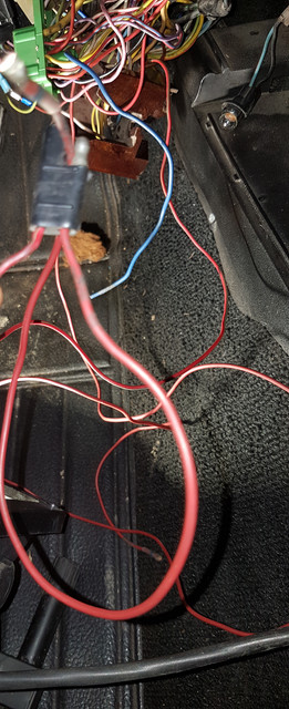
From the green "glove" there is an all red cable that goes to male pin on the part that goes in to the tach.

And the other one that goes from saftybox to the female part is red and green.

I.e the right one on the pic is the cutted one and the left one is the red-green one

Impossible to get a 1,5 Ohm resistor so i got a bag of mixed ones. Did a combo of 10 resistors and got it down to 2 Ohm (not the right value and i dont know if that is a good idea/allowed or if i still need to try it with a single resistor that is 1,5 Ohm. However the car did start) and the tach is still acting dead.


Last edited by a moderator:
Got the resistor today 1,5 ohm 0.5 watt, attached it, turned on the key and smoke came from the resistor directly. So i guess i need more than 0.5 watt.

The electrician didn't think/guessed that the tach had burned just because someone took away the resistor.

Also screwed apart the tach. Couldn't see any obvious errors.

Ill be back when i get the new resistor. Any tips of which watt i need would be helpful so i don't have to buy every resistor from 1-20 watt or 50???

 
You need a ballast resistor made for automobiles, an electrician should have been able to figure out what the current draw is across a resistor, based on the ohms of the primary side of the coil. You probably need around 80 watts to have a little safety factor.

https://www.summitracing.com/parts/sum-g5218?rrec=true

 
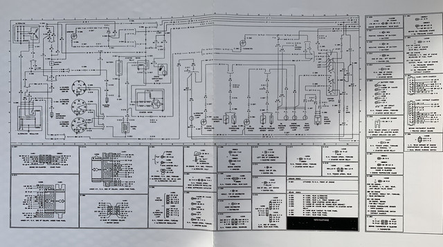
Here’s is the page from the Scott Drake reprint of ‘73 wiring showing the tach. I hope it helps. No, I’m not qualified to answer any questions - lol. Tach is located at B-11


Thanks for the wiring. I got almost the same, only, my doesnt have the small pics that is around yours. 1 question anyhow, I cant read the letters on the small pics. Does it say somewhere any values/numbers for resistors or the tach on the small pics under the wiring diagram?


Latest posts

Back
Top