Holley Sniper EFI and RobbMC Surge Tank, 351c and FMX

7173Mustangs.com

Help Support 7173Mustangs.com:

This site may earn a commission from merchant affiliate links, including eBay, Amazon, and others.
What is the car idling at?  Higher idle is usually a sign that the throttle plate is not set up properly or you have a faulty IAC motor.  You will have residual fuel in the plenum and if the IAC motor is allowing sufficient air in you could have dieseling if the fuel octane is too low.  The idle solenoids in the carb systems were used to close the throttle plates to avoid dieseling by choking the air flow similar to a IAC motor in TBI systems.
I have the idle fluctuating from around 680-800 when in drive. Should I have to run 94 octane for an engine with a supposed 9:5:1 compression ratio? (as a note that's the compression ratio I was told by the guy who spec'd out my engine. I have 2v aussie closed wedged chamber heads, dished pistons and a mild cam) Also any input on the backfire and stall when I floor it from a stop? Thanks
What is the CC on the heads? Were they worked at all to open them up? How large is the dish in the piston? I have the aussie 2v's that I had worked and opened up to right at 60cc. My dished pistons if I remember correctly were just over 4 cc including the valve relief. That put my compression around 10.4:1. I can run 91 or 93 octane with no ping and a fairly aggressive cam. Have you checked to make sure your timing marks are in the correct location? Bring the "1 piston to TDC and see if it is lined up at the "0" on the timing marks to make sure your timing readings are accurate.

 
What is the car idling at?  Higher idle is usually a sign that the throttle plate is not set up properly or you have a faulty IAC motor.  You will have residual fuel in the plenum and if the IAC motor is allowing sufficient air in you could have dieseling if the fuel octane is too low.  The idle solenoids in the carb systems were used to close the throttle plates to avoid dieseling by choking the air flow similar to a IAC motor in TBI systems.
I have the idle fluctuating from around 680-800 when in drive. Should I have to run 94 octane for an engine with a supposed 9:5:1 compression ratio? (as a note that's the compression ratio I was told by the guy who spec'd out my engine. I have 2v aussie closed wedged chamber heads, dished pistons and a mild cam) Also any input on the backfire and stall when I floor it from a stop? Thanks
I would think that 94 octane for a CR of 9.5:1 is more than enough.  I run 92 octane with a CR of 10.5:1 with no pinging.

As far as the backfire, I had a backfire through the Throttle body during hard acceleration and through the exhaust (popping) on sudden release of the throttle.  The solution for my system was to increases pump squirt on hard accel and for the other to adjust "power valve enrich" to assist in manifold pressure transitions. The PVE works by adding fuel based on MAP transitions while moving the throttle.

Each systems has different ways to adjust these settings and these settings fixed the backfire/popping issues for me.
I'm concerned the 94 octane is masking another problem as I shouldn't need that high of an octane.. Even when I use 92 it diesels. I thought about retarding timing, but if the car isn't pinging at all could timing really be that far off to backfire? It's odd to me that both the carb and the new EFI have the same issues under hard acceleration from a stop and dieseling. (Note the car hasn't died when cruising then going full throttle. Just from a dead stop) 

Additionally, I am very new to EFI so not sure how to adjust pump squirt or PVE, haven't been able to find any settings for that on the handheld. I will look further into it thanks for the response!

 
I have the idle fluctuating from around 680-800 when in drive. Should I have to run 94 octane for an engine with a supposed 9:5:1 compression ratio? (as a note that's the compression ratio I was told by the guy who spec'd out my engine. I have 2v aussie closed wedged chamber heads, dished pistons and a mild cam) Also any input on the backfire and stall when I floor it from a stop? Thanks
I would think that 94 octane for a CR of 9.5:1 is more than enough.  I run 92 octane with a CR of 10.5:1 with no pinging.

As far as the backfire, I had a backfire through the Throttle body during hard acceleration and through the exhaust (popping) on sudden release of the throttle.  The solution for my system was to increases pump squirt on hard accel and for the other to adjust "power valve enrich" to assist in manifold pressure transitions. The PVE works by adding fuel based on MAP transitions while moving the throttle.

Each systems has different ways to adjust these settings and these settings fixed the backfire/popping issues for me.
+1 This is a good advice. Play with your accelerator pump settings, specially the hard accelerator.

With my system I get backfire when I run with open exhaust cut-outs. I think this happens because the backpressure drops behind the O2 sensor. The instructions recommend at least 18" between the exhaust tip and O2 sensor. With the cut-out open there are about 3". The other issue is that the settings between running regular and open exhaust change suddenly so the system can't handle the open exhaust that well because this is seldom used.
There are accelerator pump settings on an efi tbi? Was not aware of that, will ask some Holley techs about it to see how I can adjust it. I think my O2 has proper placement, and my cut outs are around 25" away from the O2 sensor so not too worried about that!

 
What is the car idling at?  Higher idle is usually a sign that the throttle plate is not set up properly or you have a faulty IAC motor.  You will have residual fuel in the plenum and if the IAC motor is allowing sufficient air in you could have dieseling if the fuel octane is too low.  The idle solenoids in the carb systems were used to close the throttle plates to avoid dieseling by choking the air flow similar to a IAC motor in TBI systems.
I have the idle fluctuating from around 680-800 when in drive. Should I have to run 94 octane for an engine with a supposed 9:5:1 compression ratio? (as a note that's the compression ratio I was told by the guy who spec'd out my engine. I have 2v aussie closed wedged chamber heads, dished pistons and a mild cam) Also any input on the backfire and stall when I floor it from a stop? Thanks
What is the CC on the heads? Were they worked at all to open them up? How large is the dish in the piston? I have the aussie 2v's that I had worked and opened up to right at 60cc. My dished pistons if I remember correctly were just over 4 cc including the valve relief. That put my compression around 10.4:1. I can run 91 or 93 octane with no ping and a fairly aggressive cam. Have you checked to make sure your timing marks are in the correct location? Bring the "1 piston to TDC and see if it is lined up at the "0" on the timing marks to make sure your timing readings are accurate.
Will go check after dinner and report back on the head specs! I heard somewhere that my stock timing marks won't be accurate with a modified engine? Am I imagining things? What would throw the timing marks off? I will try retarding timing, but since I hear no pinging I don't think it could be THAT far off to where it would backfire out of the throttle body... right? Thanks !

 
For sniper its under Tuning : Basic : Basic Fuel => acceleration enrichment.  Higher the number more the pump squirt.  Increase it slowly, test, repeat until backfire stops.

 
For sniper its under Tuning : Basic : Basic Fuel => acceleration enrichment.  Higher the number more the pump squirt.  Increase it slowly, test, repeat until backfire stops.
Oh awesome! Could this make it worse? Was initially worried that the TBI was flooding under hard acceleration causing the car to stall.
Yeah it could, I always reference my set up (290 duration cam) and I wasn't getting enough gas.  You could lower the setting a little and see what happens.  You will tell immediately if you are going in the wrong direction.

I was looking at the manual and this system has a lot of adjustability.   One thing I noticed that you can adjust the fuel (prime) the motor get during cranking, my system doesn't have that feature and I wish it did.

Go in with patience and play with the numbers and test. Go up or down in low increments and then test.

Sent from my SAMSUNG-SGH-I337 using Tapatalk
Alright sounds good thanks guys! @jbojo yea the sniper seems to come with a lot of different parameters that I can adjust some I'm excited to learn them all! Did some research, what is happening does sound like a "lean cough" so I will try increasing a little bit  ::thumb::

 
Another week passed and I'm still waiting for the fittings of my fuel line...

I needed do non mustang related things too but managed to find some time to come back to that Lokar kickdown thingy...

Here's the bracket I should have received with the Lokar cable KD kit for FMX.


On this pict showing the bracket done and the one provided by Lokar...

The provided bracket is a joke (bad one), It will never pull the lever the way it should.

I've promised Adam to give him the bracket drawings. But as more will have the same prob at some point,

I thought I extend a bit more... I've a pdf here: http://www.closier.nl/downloads/mustang/FMX_KD_bracket.pdf

that should help you make it.

You'll need a plate of metal strong enough to handle the pull as the bracket needs roughly 7.5 cm offset to be in line with the trans lever.

It doesn't have to be super strong either, the shape is large where the pull force is done. I went for 3mm thick aluminum.


Here using the dummy I did after measuring everything, I've taped the plate so it doesn't get scratches and also to ease the reproduction

of the shape with a pencil/marker. (The pdf once printed would become your dummy)

First is to mark the holes and bore them. The diameter is slightly above your screws on the pan side and the lokar end fitting on other side.

in some cases, if the pan is original, the first screw is really near of the pressed metal, so as on the pdf drawing, you may need open that hole

vs having just a hole like me so it fits (bracket flat on pan). Then time to cut the contour. For aluminum, use raw wood blades if you do not have aluminum ones.

and cut at low speed so your blades do not fill with the metal. Fine tune the shape, polish, sand etc...

For the folding, take your time: aluminum would get tired very quickly and even break. To get the shape as on example above

you need that the first fold fits the very narrow side of te pan including the thickness of the metal. Using 3mm the drawing is fine.

if you use thicker, you will need to move the fold toward the pan by the difference. The first fold is there to let the shifter and steering brackets to move

with no interference with the cable, the second for the cable tensor, needs be paralel, it will then land +- 3.5 cm from the lever nipple

as in pdf, the distance from first pan hole on bracket aligned to center of hole of tensor, is 7.5 cm.


This is the result once in place (A). In my case, as the Snipper throttle axle gives a traveling distance of 3.3 cm at max, while the lever travels 2.6

I decided I'd be better off reducing the cable itself, and simply place a the nipple on the unit towards the center a bit.

Trans side, I opted to correct the small gap needed by reducing the length of the hardware provided vs making the bracket bigger.

In case you have plenty space and/or you do not want to modify the cable, just move the fold (and the hole) (B).


Here is the min and max after correction. It's time to secure the remaining screw on cable.

and Voila! No hanging cable, in line with lever, and full pull.

 
Last edited by a moderator:
A new episode of my Sniper install:

My fuel fittings and hoses finally arrived, so time to go back to where we were...

Weather was super nice, and as its Holland, you know this is not gonna last long.

So next on the todo was the tank. In order to replace the vent cap with the (expensive) sending unit.

Before to do so, the excess fuel needed go out, so I've lowered the old fuel line to floor level,

and jacked up the car from the rear. After +- 1.5 gallon was removed, I've remove the sending unit hose, and continued at the tank

another 1/2 gallon went out. Then removed the old fuel lines fittings and the line itself.


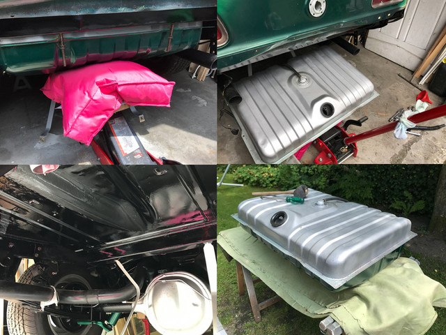
I knew for past experience when i've repainted the tank that removing it is something that requires 4 hands.

As i'm alone working on the car, I got my extra hands by using my large floor jack with a large piece of wood and a pillow to spread the weight.

Lifted a bit, then after the straps were loose, let the hydraulics do the work, and there it was.

Note that if you never removed the tank before, I strongly suggest you oil the straps studs and nuts days before you work on the car.

These are very tricky to get out when they are rusty (and they are rusty 99% of the time).


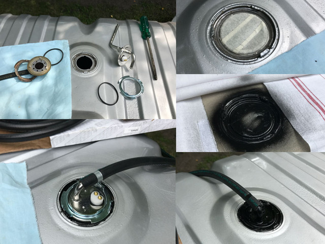
The vent cap need be tapped out gently, and I've discovered also that the sending unit doesn't fit. Noooooooo!

Unlike the pict send by Adam, the 73 tank as 3 lips evenly spread, while the sending unit has two.

So needed mutilate that poor sending unit bits more, and kept one, just to say I keep one for the $ i've spend on that stoopid tube :)

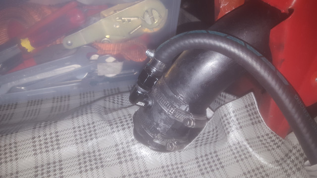
As the vent cap collected dirt, before clean up, I've taped it so no dirt enters the tank. Then cleanup up. primed and painted the groove, then once dry

installed the sending unit, placed the hose and painted the entire install.

Why? Because i'm far from California and anything left blank will rust in no time over here.

Reinstalling the tank is easy too, tho, take care push it bit more to rear of the car as the new nipple is slightly higher than the vent cap.

And clean/grease the straps studs/bolts, you'll be happy next time. Mine were still perfectly greased, so all that went as butter.


If you saw the Holley vids on sniper install, easy pizzy, you done in 5 minutes... not! It's now ideal while the tank is out to study

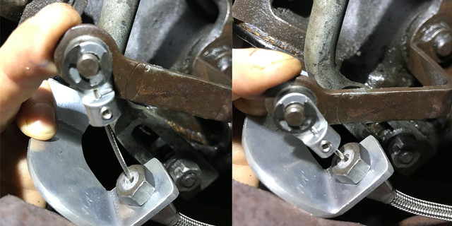
how and where you're gonna place the pre-filter and the pump. The space we have COULD be ok if the

sending unit nipple was pointing the other way, unfortunately, unlike the Camaro on the video, we can't place the pump

behind tank either, unless you would add a significant loop of hose as you would first need to go back toward middle of the car.

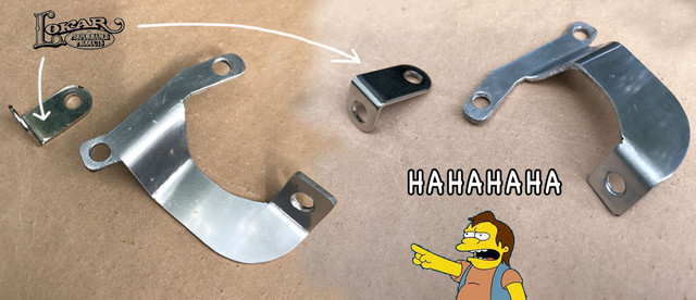
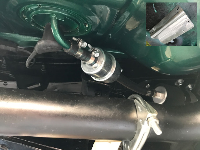
As I go by the old fuel line route, the only way to do that, is to make a bracket: yes another bracket!

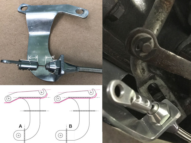
On our bodies, no way to fix it on the rail without a faulty alignment with the sending unit, plus we need the pump to be

the lowest possible and near the tank.

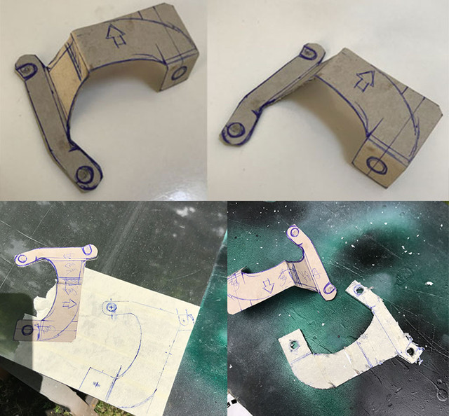
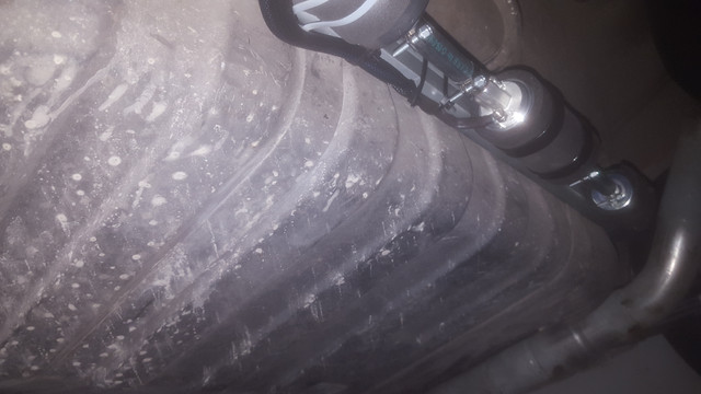
So the bracket must lower the pump +- 2.5 inch and offer a way to align the pump. (top right on pict, before i've painted it)

Made of 3mm thick alum plate, because its 13 cms long and need two folds, you need some serious force to shape it.

If you can form it by hand, stop and pick thicker metal, it must be secure.

I'm half way there, the other side of the bracket, will allow me to complement it with a light aluminum plate

so the pump and bracket will be isolated from heat and the elements. (more picts when I'll do that part)

It will also secure the first fixation of the return line together with the feed line.

During paint drying times, drilled baie wall for the 90 degrees fuel ends (see picts from last week) and prepared the unit braided hoses.

I should be able to install these babies tomorrow.

To be continued...

 
Last edited by a moderator:
Nice! Do you have a more info/picts of your install?

Detailed pict of your KD construction from side would be interesting to look at too... looks like you kept the original lever for this.

On my side, almost done, waited 3 weeks to get my fuel fittings and got nasty surprise few were wrong sized...

Another week past and while I already received 1/2 of the wrong corrected. Still 2 missing... grr

No biggy tho, as I redid some time consuming brackets for the fuel pump housing and have other 'must do' stuffs on the car

before it can leave the garage anyway.

 
Last edited by a moderator:
Nice! Do you have a more info/picts of your install?

Detailed pict of your KD construction from side would be interesting to look at too... looks like you kept the original lever for this.

On my side, almost done, waited 3 weeks to got my fuel fittings and got nasty surprise few were wrong sized...

Another week past and while I already received 1/2 of the wrong corrected. Still 2 missing... grr

No biggy tho, as I redid some time consuming brackets for the fuel pump housing and have other 'must do' stuffs on the car

before it can leave the garage anyway.
Thanks Il get some pics tonight :)

Regards Rob

 
Okay

Here are some pics, I made the levers of a bit of tubing I bent. The rest is just basic stuff I had in the garage. But it works great.

Fuel pump pressure line on passanger side and return line on drivers side.

I hade an aluminum bar from curtain that I used to mount the filters and pumps to

The return line is direct into the goose neck. I took the neck out and drilled it. I bent a piece of metal the same shape as the tube, and drilled a hole into it. Then I fitted the AN coupler. I used alot of Silicone so when compressing the metal piece with clamps it sealed Everything. I cheap solution but it works for now.


vid.mp4


Attachments

  • vid.mp4
    3.1 MB
Last edited by a moderator:
Okay

Here are some pics, I made the levers of a bit of tubing I bent. The rest is just basic stuff I had in the garage. But it works great.

Fuel pump pressure line on passanger side and return line on drivers side.

I hade an aluminum bar from curtain that I used to mount the filters and pumps to

The return line is direct into the goose neck. I took the neck out and drilled it. I bent a piece of metal the same shape as the tube, and drilled a hole into it. Then I fitted the AN coupler. I used alot of Silicone so when compressing the metal piece with clamps it sealed Everything. I cheap solution but it works for now.


Awesome work! Cool seeing how both you and Fabrice have used ingenuity to make your kickdowns work. (I still have yet to put mine on and am manually downshifting) 

As for my dieseling issue that I brought up a couple posts back, sounds like the fact I used the 12v ignition source form the old antidieseling device is the problem as it is keeping the Sniper running just a little longer after the ignition is turned off (shoutout to Fabrice for this theory). Was wondering what ignition source you used Robsweden?

 
An issue I am currently having with the car is that at light acceleration, the car is making a constant stream of muffled pops (not conventional backfire loud) right around 2000 rpm. The car idles well, accelerates well at WOT and doesn't seem low on power. However, when these pops are occurring I do feel some engine hesitation it feels like. Any ideas? Others I have talked to believe it could be running lean, but my AFR seems to be right sitting at a solid 13.5 at these times.

 
Okay

Here are some pics, I made the levers of a bit of tubing I bent. The rest is just basic stuff I had in the garage. But it works great.

Fuel pump pressure line on passanger side and return line on drivers side.

I hade an aluminum bar from curtain that I used to mount the filters and pumps to

The return line is direct into the goose neck. I took the neck out and drilled it. I bent a piece of metal the same shape as the tube, and drilled a hole into it. Then I fitted the AN coupler. I used alot of Silicone so when compressing the metal piece with clamps it sealed Everything. I cheap solution but it works for now.


Awesome work! Cool seeing how both you and Fabrice have used ingenuity to make your kickdowns work. (I still have yet to put mine on and am manually downshifting) 

As for my dieseling issue that I brought up a couple posts back, sounds like the fact I used the 12v ignition source form the old antidieseling device is the problem as it is keeping the Sniper running just a little longer after the ignition is turned off (shoutout to Fabrice for this theory). Was wondering what ignition source you used Robsweden?
Hi
Im using msd 6al box with msd distribuitor no vacuum advance. All the wiring is replaced with eazy wiring harness.

Regards Rob

Skickat från min SM-T815 via Tapatalk

 
Nice piece of solid mechanic for the KD Rob!

Ah I bet you went passenger side, because of the direction of the sending unit nipple forcing a loop if you would go old line route...

I hesitated do same thing and opted for the "all on one side", tho also means more complex bracket work as you can't fit

the 2 filters+pump in the safe space left over and it need be well encapsulated from the elements. so second filter is now relocated near wheel before entering bay.

I wished I opted for the other side at times :D

I'll post final picts of the whole line work when I finally will be able turn that key on.

How does your lines enter engine bay from the sides or you went back to tunnel? As you have inverted sides for the unit ports, where do they cross each other?

Also for you positive wire where did you tab the power? found the red green wire at ignition on column that would do, but wonder if there not another place

to do it, saving me the gym to solder the splice safely on the spot.

 
An issue I am currently having with the car is that at light acceleration, the car is making a constant stream of muffled pops (not conventional backfire loud) right around 2000 rpm. The car idles well, accelerates well at WOT and doesn't seem low on power. However, when these pops are occurring I do feel some engine hesitation it feels like. Any ideas? Others I have talked to believe it could be running lean, but my AFR seems to be right sitting at a solid 13.5 at these times.
Where is your timing when this happens? I would richen it to 12.8 to 13.0 and see what happens. The other cylinder bank may be running leaner.


Latest posts

Back
Top