Totalled's rebuild thread

7173Mustangs.com

Help Support 7173Mustangs.com:

This site may earn a commission from merchant affiliate links, including eBay, Amazon, and others.
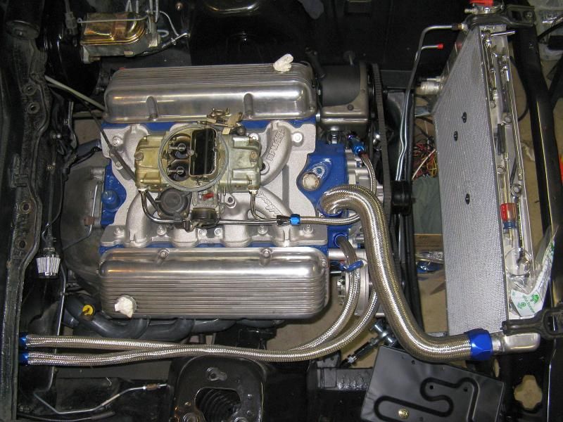
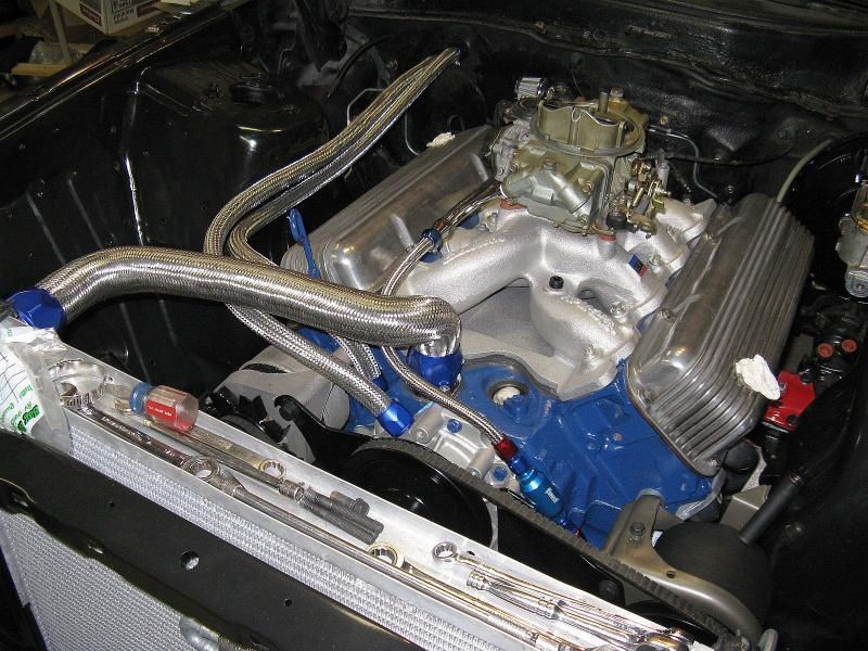
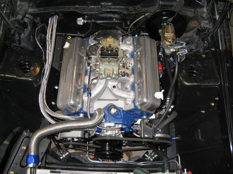
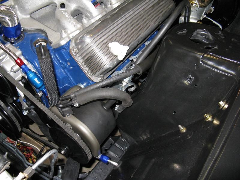
Pressed the power steering pulley on. Also started on the hoses. That stainless braid is a pain in the fingertips.. If it didn't look cool to me... forget it.
Yeah I agree with you on those stainless braided lines. They look good but they are a pain in the butt to get those connectors on. I didn't have a good cutting tool for the lines so I was always fighting with them. Looks like you are getting close to firing her up.

 
Lunchtime update: Got the heater hoses done.

IMG_0790_zps1063d234.jpg


IMG_0791_zpsbcbcb91c.jpg


Lunchtime update: Got the heater hoses done.

IMG_0790_zps1063d234.jpg
Just curious, where's the cutoff valve for the heater? By your setup you would always have heat. I am missing something, does a non AC car have that valve inside and not in the engine compartment.

 
Lunchtime update: Got the heater hoses done.

IMG_0790_zps1063d234.jpg
Just curious, where's the cutoff valve for the heater? By your setup you would always have heat. I am missing something, does a non AC car have that valve inside and not in the engine compartment.
I believe non A/C cars were controlled by a cable, not vacuum like yours and mine.

-Travis
Thx Travis. So I am guessing that its in the heater box in the passenger compartment.

 
The non A/C cars don't cut off the coolant. I guess it just diverts airflow to bypass the core.

Got the lower hose on, and power steering hoses.
Thx Pat. I got off my butt and read up on the non AC models in the shop manual and see how they do it. When I first saw this I thought that with the coolant constantly circulating that you would have residual heat bleeding into the passenger compartment. They just block the airflow over the core to isolate the heat like you and Travis mentioned. I learn something new everyday here.

BTW, when do you expect to fire her up again?

-john

 
Thanks Q.

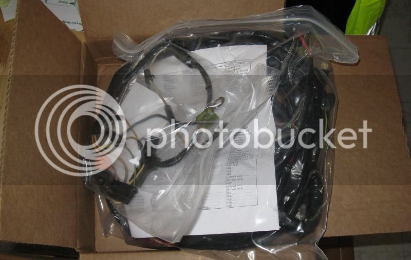
Hopefully, when I get a wiring harness back. Dropped the original drive shaft off to have it re-tubed and balanced Friday. That way I can run a 3.50 3rd I picked up, or the original 3.25 if I plan a long trip.

It is a spectre dress up kit. The Actual AN fuel components are Russell brand with a Summit Racing filter.

 
Last edited by a moderator:
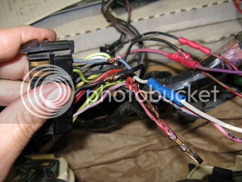
So today, I set about swapping the non tach cluster plug, for the tach instrument cluster plug, along with adding the plug and correct pigtail for the center gauges. The previous owner added the gauges by tapping into the cluster plug. I kept them tapped here so I wouldn't have to unwrap the whole harness, and re-pin the junction at the fuse block. I also cleaned up the splices.

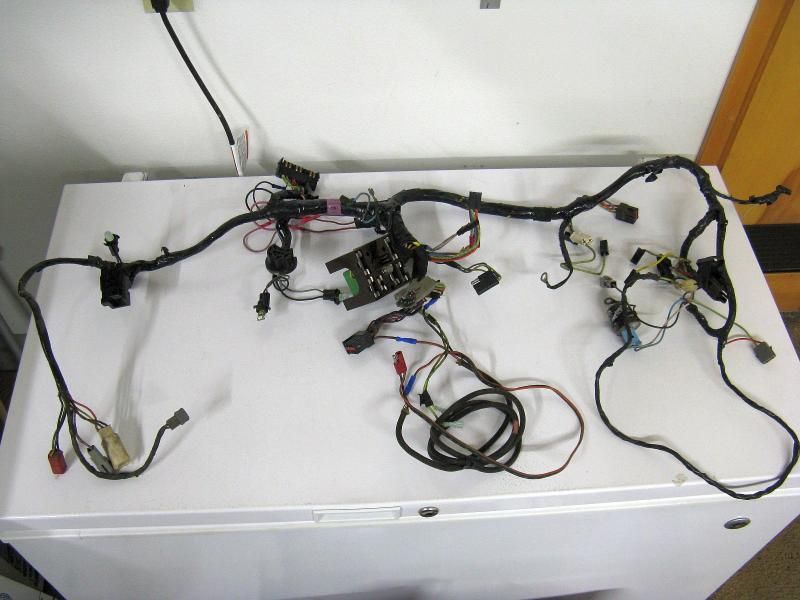
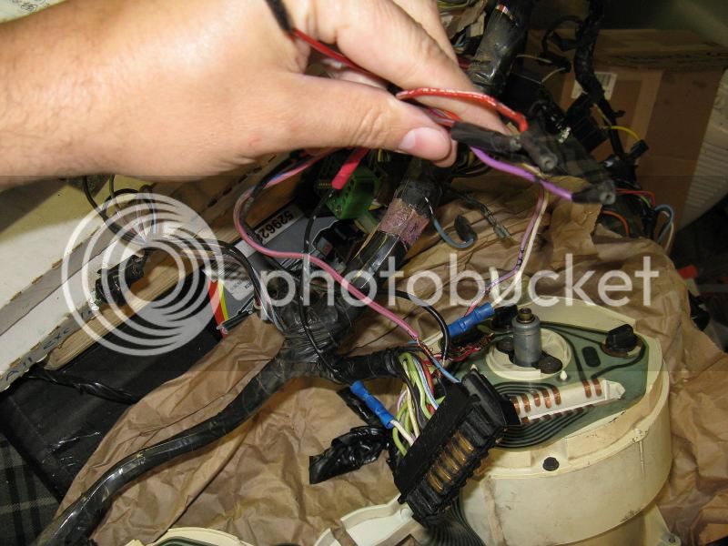
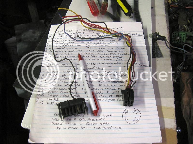
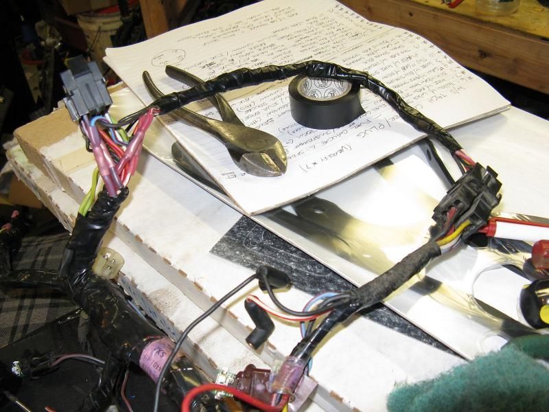
So, unwrapped tach/gauges harness:

IMG_0804_zps3b0d50ee.jpg


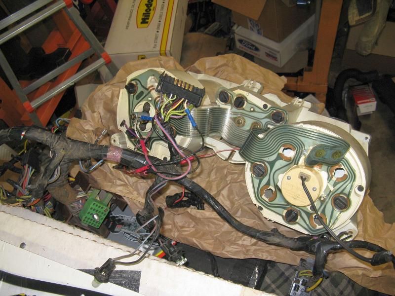
My hacked harness and cluster:

IMG_0805_zps5f00f859.jpg


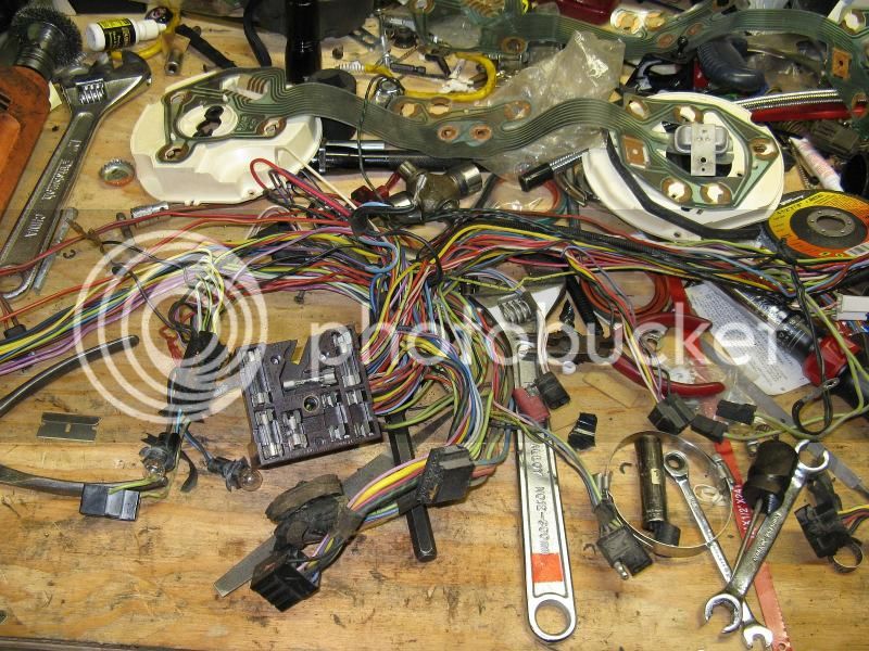
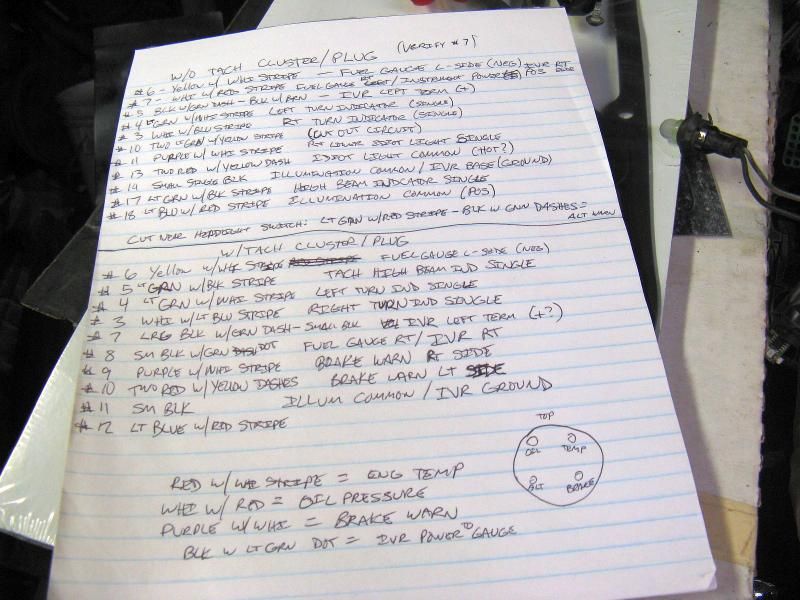
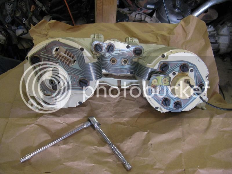
I traced all the printed circuits and matched them up to the wire positions in the two plugs and clusters.

IMG_0806_zps8b596e20.jpg


How they tapped into the harness at the cluster plug for the center gauges:

IMG_0807_zps23c015e3.jpg


IMG_0808_zpsb4585091.jpg


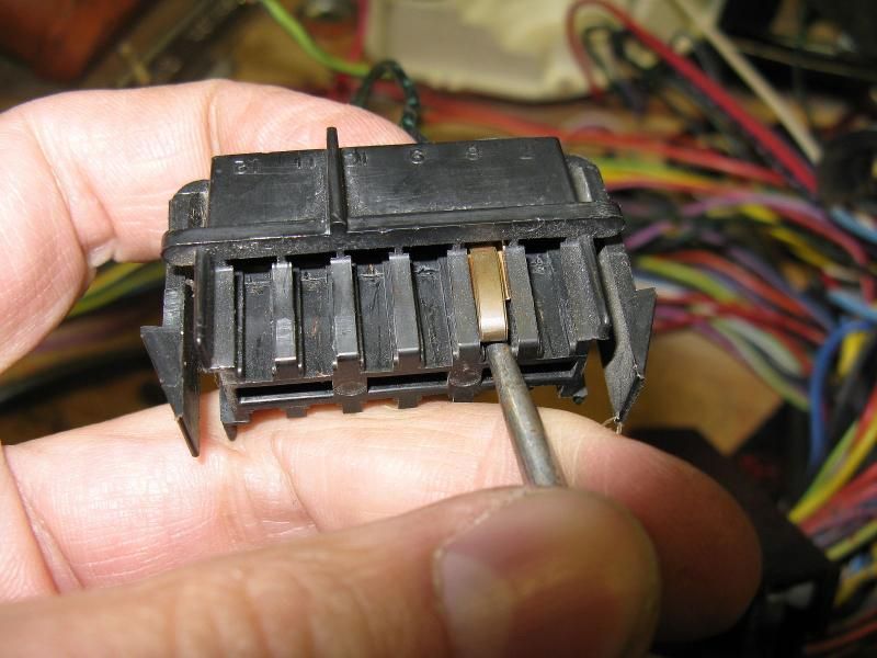
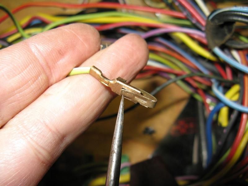
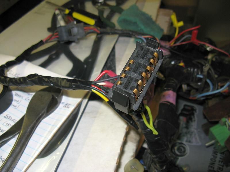
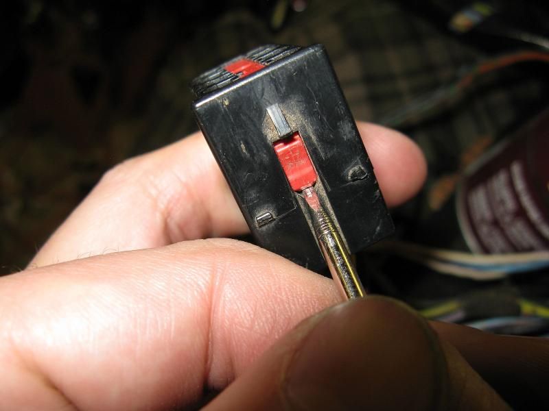
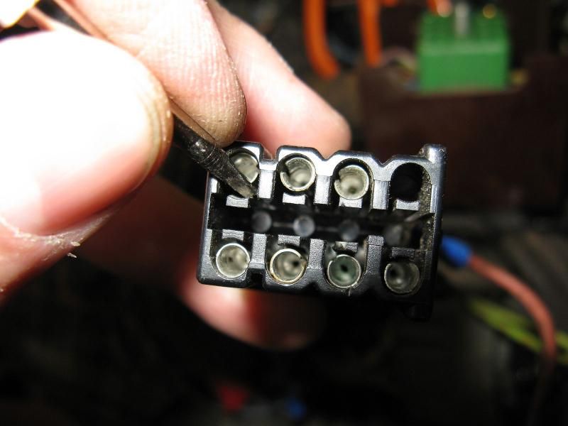
How to de-pin the cluster plugs. Shove a sharp pointed awl or thin/small flat blade screwdriver in like this to disengage the retaining tab for the contact.

IMG_0809_zps619f9bfe.jpg


This guy:

IMG_0810_zps791d1b72.jpg


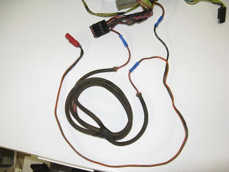
Center gauge harness with the lone wire that originally went to the plug. (+ power for the gauges)

IMG_0811_zps0571fd48.jpg


Original non gauge plug removed.

IMG_0812_zps147b58c6.jpg


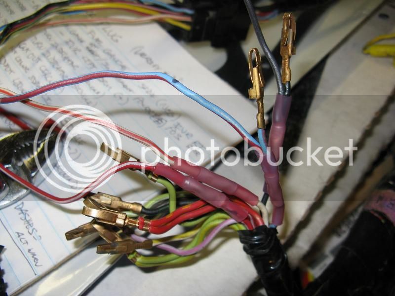
Splices done.

IMG_0817_zps669cbe94.jpg


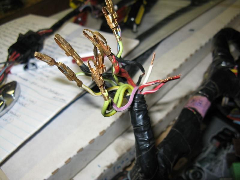
Bend the tabs back out, and start re-pinning the cluster plug.

IMG_0819_zps5c6c7704.jpg


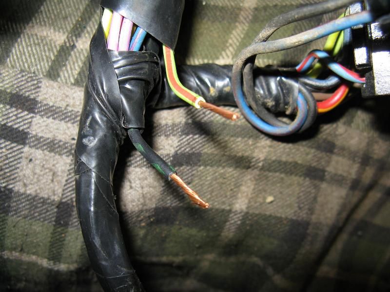
These two wires were cut off and taped up near the headlight switch plug. I think they were for the alternator warning light? Was that a separate feed/socked for the cluster and plug?

IMG_0822_zpsb89acebf.jpg


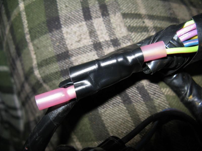
Anyway, I put butt connectors on to insulate them, and use them later if needed.

IMG_0824_zps55e81b8c.jpg


Also ended up with an extra terminal from the original cluster plug. Heat shrinked it and taped it out of the way.

IMG_0825_zpsbe652fc2.jpg


End result:

IMG_0826_zpse621ccc0.jpg


IMG_0827_zps880fe4eb.jpg


Nice progress Pat. I don't envy the amt of work and patience that you are putting into the electrical portion of your build. Looks like you're keeping good notes as you tear into this. Getting closer each day to getting her back on the road.

-john

 
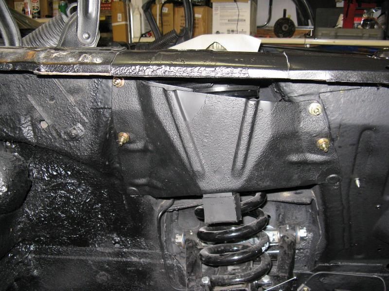
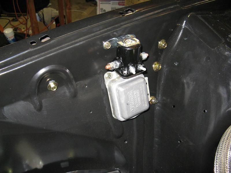
Well, today I painted and put in the spring cover/shock tower brace I got from Mike. Love those California parts. Also installed the voltage reg and starter solenoid.

IMG_0839_zps35af070d.jpg


IMG_0840_zps7f5353fb.jpg


Also found that the body shop did not transfer the plate and mounting nut for the horn on the LF apron, and that the holes punched in that repo for the washer bottle screws... are larger than the screws... :rolleyes:

Also found that the shock tower cap hardware is not included in the master body fastener nor under hood detailing kits... So there's another order... Hardware store carriage bolts do not fit. The heads are too thick for them to slip in.

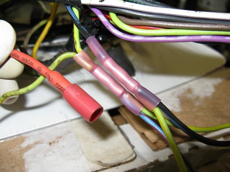
So, I hopped back onto the under dash harness. I decided to unwrap the plug/wires for the dash map light. Glad I did...

IMG_0828_zps52fe7d3b.jpg


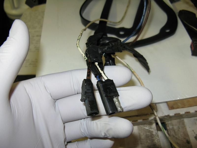
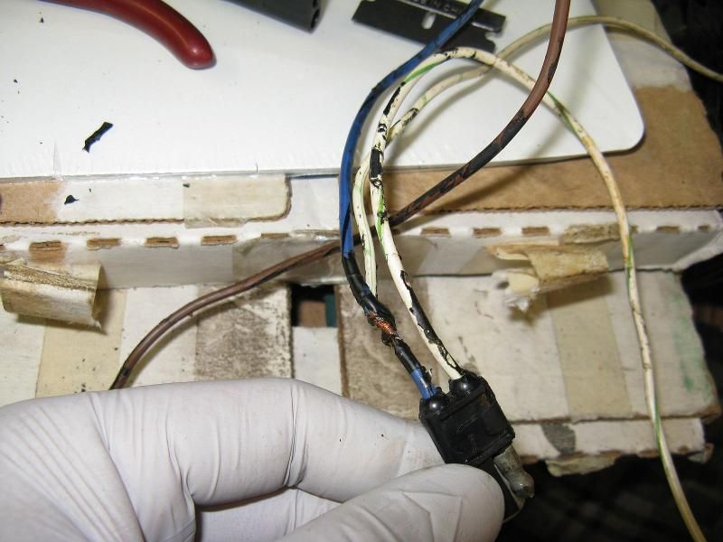
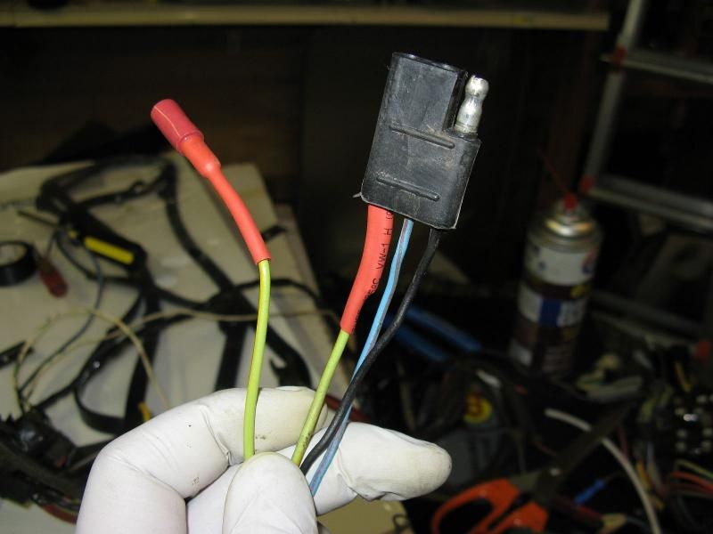
They made it out of two different plugs.. And had an awesome splice in it to feed the glove box light...

IMG_0829_zpsb4de5156.jpg


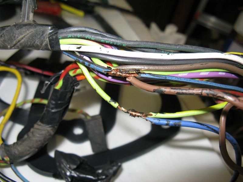
And of course, awesome splices in the main harness to power it...

IMG_0830_zpsbd5d5d57.jpg


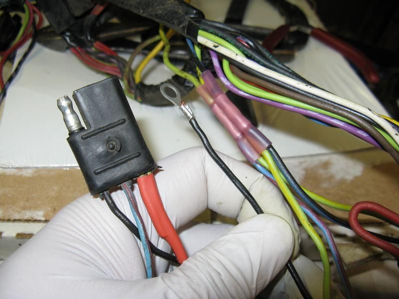
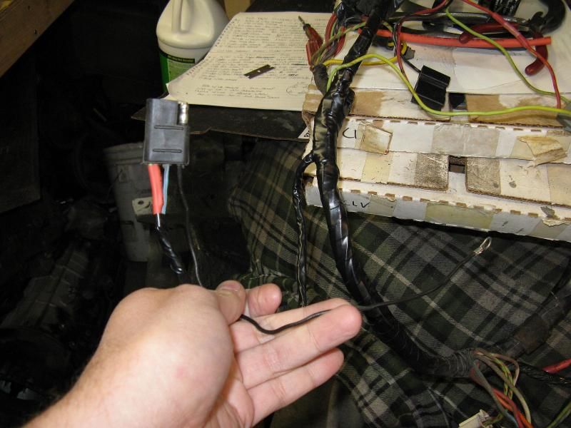
So I clipped the clock plug out of the tach, now donor harness to fix it. And ran a new wire/plug to feed the glove box light.

IMG_0831_zpsac86cb02.jpg


IMG_0832_zpsf931c7fc.jpg


IMG_0833_zps2f74daad.jpg


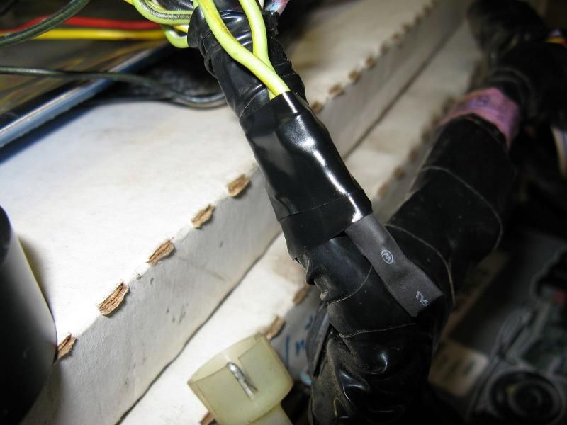
All wrapped up.

IMG_0841_zps692fd448.jpg


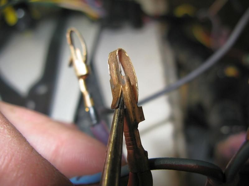
I had to repair the main power wire into the ignition switch plug. So, I popped it out of the plug to slip some heat shrink tube on it. This is how you do that.

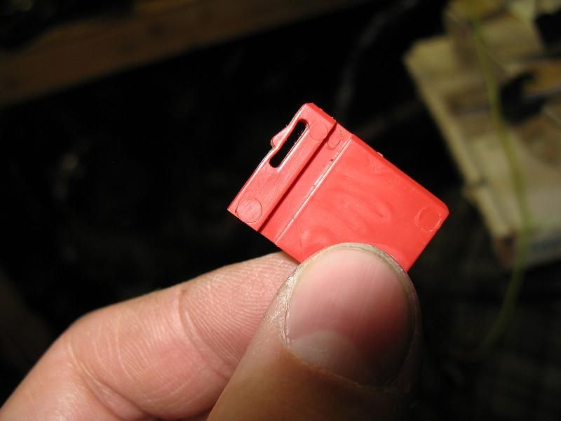
Take a small flat blade or awl and pry this red piece up:

IMG_0838_zps3b2b3195.jpg


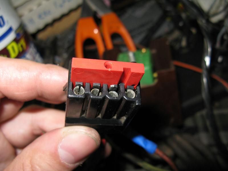
It has a little tab you have to push in after you pry it up some, to get it the rest of the way out.

IMG_0836_zps6efb97d2.jpg


After that, it pops out.

IMG_0837_zpsdaf54f74.jpg


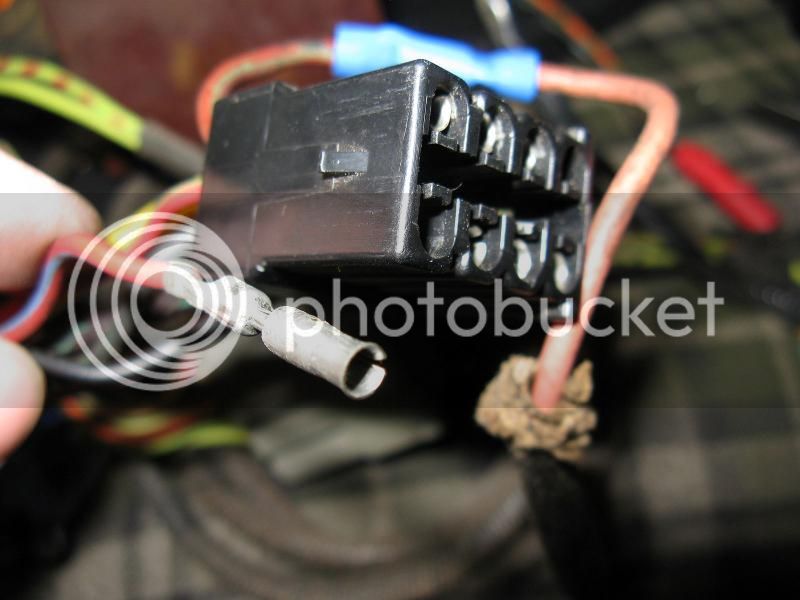
After that, pry these tabs inward on the plug to release the terminal you want to remove:

IMG_0834_zps97571bb7.jpg


Then you can pull it out.

IMG_0835_zps6bf8282c.jpg


Ta-da. :D

 
Today was frustrating. No one in town had rear wheel bearings in stock. The repro muffler hangers had the holes 1/2" too far apart. Not sure if they changed in '73 or if it's a repro thing.. There definitely was a repro thing with the replacement center gauge bezel. The holes were too far apart for the cargo pocket, to narrow for the map light, and the pedestals for the gauge mounting screws were different heights..

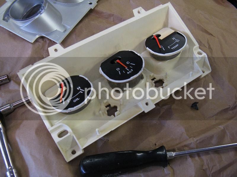
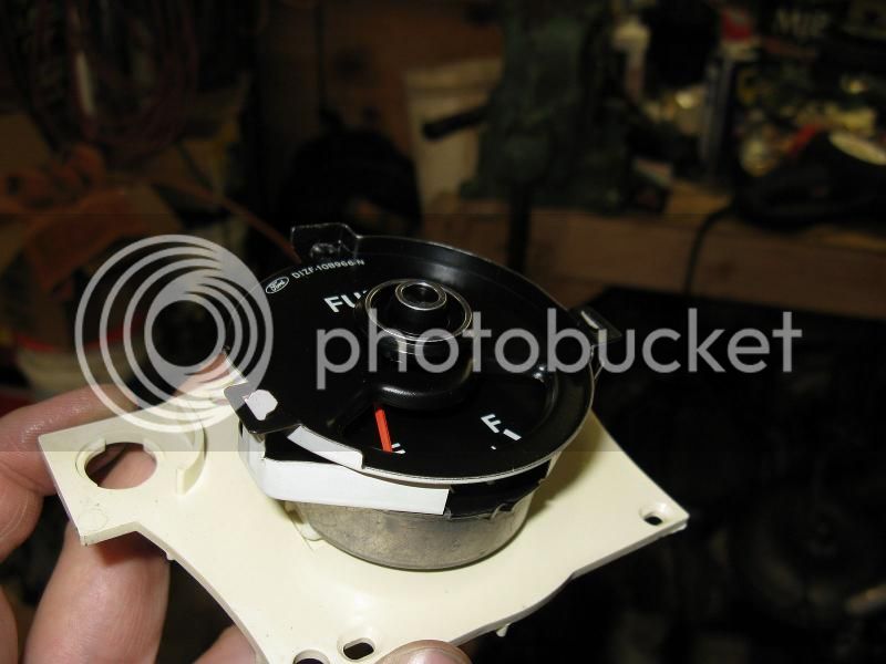
I assembled the cluster today. I previously trimmed the side shielding from the gauges to allow more light on them to make them brighter.

IMG_0842_zps31abb738.jpg


IMG_0843_zpse9ffff59.jpg


IMG_0844_zps3c659d34.jpg


IMG_0846_zps855765d5.jpg


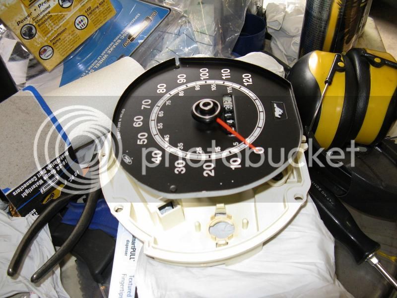
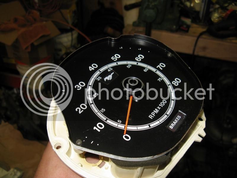
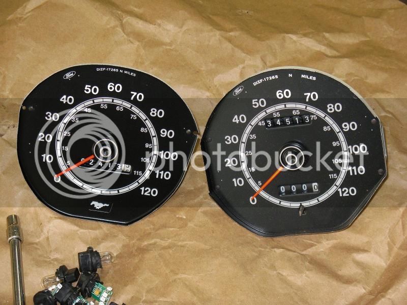
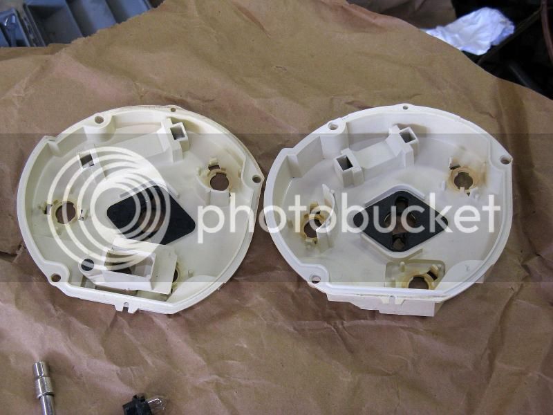
Here's some differences between the tach and non tack speedo and backing plates:

IMG_0847_zps6670fe2e.jpg


IMG_0848_zps19c64a3b.jpg


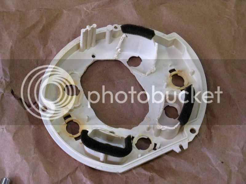
And the hacking they did to my idiot lights to fit the tach in there:

IMG_0849_zps6f2621c8.jpg


So, I took my speedo, and stuck it on a tach cluster backing plate, and took my tach and put it on the proper tach backing plate. It's basically a factory tach cluster now minus the trip odometer.

IMG_0850_zps98d00b96.jpg


I left off tonight with the dash harness set back in place. Still need to finish routing it and plugging everything back in.

 
Last edited by a moderator:
Nice progress today Pat, looks like you're are almost done with the electrical mods. BTW do you know what the voltage coming off the constant voltage regulator should be? I am still trying to troubleshoot my engine temp gauge issue. I heated the temp sensor with a heat gun and watched the resistance start changing as it cooled off so I know that that is good. I just need to know what the voltage is at the terminal of the gauge from the VR.

thx

-john

 
Wow that old harness was a little scary. With all that splicing I am surprised there were no unwanted sparks going on! Either way it looks like Midlife came through! Have fun putting it all back in.

 
Back
Top